
This article is one of a multi-part series on setting up a segregated Guest Network, including a guest WiFi network, within a Home Network. It is essentially an introduction to Virtual Local Area Networks ( VLAN), provides a simple use case for VLANs and gives a complete set of recommended hardware plus details the setup of that hardware.
The series of Guest Network articles progresses as follows:
- We select a set of low cost hardware to meet our criteria of creating a Guest Network, including Guest WiFi, within our Home Network.
- We go into some detail why we use VLANs and a managed switch. Understanding VLANs is key to understanding how to build a guest network.
- We set up the TPLink TL-WA801N WiFi Access points. This is a very simple process where configure each AP onto our Home Network and configure the AP's WiFi to operate on our separate Guest Network VLAN.
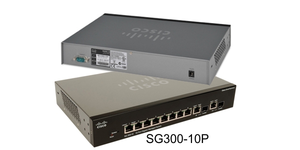
- We set up our managed switch, a Cisco Linksys SG300-10P, to send Home Network traffic to only the Home Network devices and Guest Network traffic to only the Guest Network devices. And we show the special case of mapping the Guest Network Access Points onto both networks simultaneously.
- We begin preparing our main router, a TPLink TL-WR1043ND, to create and manage the VLAN traffic for our Home Network and our Guest Network. Since the WR1043ND does not come with 802.1q VLAN support out of the box, this article is where we install openwrt on the WR1043ND.
- Lastly, we configure openwrt on the TPLink TL-WR1043ND to create and manage all the VLAN traffic.
In this article of the series, Part 4, we'll configure the Cisco Linksys SG300-10P managed switch to thoughtfully send traffic to devices on our Home Network and our Guest Network.
VLANs to Be Used
Our system will be using the following VLANs:
- VLAN1. The home network at 10.32.147.X. These devices are all our personal devices include laptops, desktops, phones, printers, etc.
- VLAN2. On the TPLink WR-1043ND router, VLAN2 is the WAN port. This is connected to a cable modem in our case.
- VLAN4. This is the guest network at 10.32.148.X.
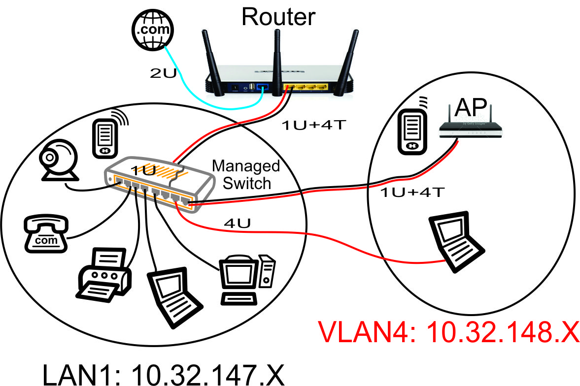
The above network diagram shows how we will be defining the ports on our Cisco Linksys SG-300-10P Power Over Ethernet (PoE) managed switch.
Our guest WiFi Access Point is shown in the upper right hand corner. This Access Point will hand out WiFi IP addresses in the guest network range of 10.32.148.X. To make it easy to configure the Access Point from our home network, we will put the AP's web configuration page on our home network with the 10.32.147.X range. This will prevent guests from being able to modify the AP settings.
We will also create a port on the managed switch that will allow a guest to plug into a wired Ethernet connection and automatically be connected to the VLAN4 10.32.148.X guest network.
Set Up the Managed Ethernet Switch
The Cisco Linksys SG-300P managed Ethernet switch will be minimally configured as follows:
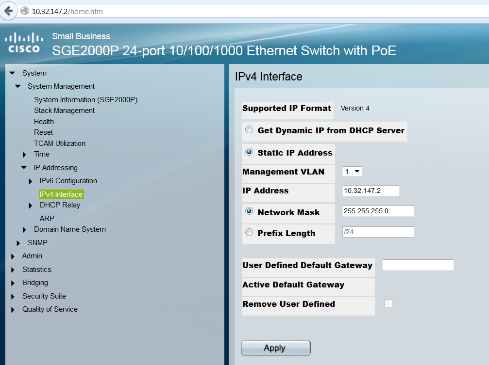
- Set its web configuration IP address at a fixed address on the 10.32.147.X primary home network.
- Configure the port that is connected to the router to accept untagged VLAN1 traffic and tagged VLAN4 traffic.
- Configure the port that is connected to the guest access point to accept untagged VLAN1 traffic and tagged VLAN4 traffic.
- Configure the port that is connected to the guest Ethernet jack to accept untagged VLAN4 traffic only.
Please note: for some reason, I cannot use Google Chrome (my preferred browser) to access the SG-300P configuration web page. I use Firefox instead. Hmm....
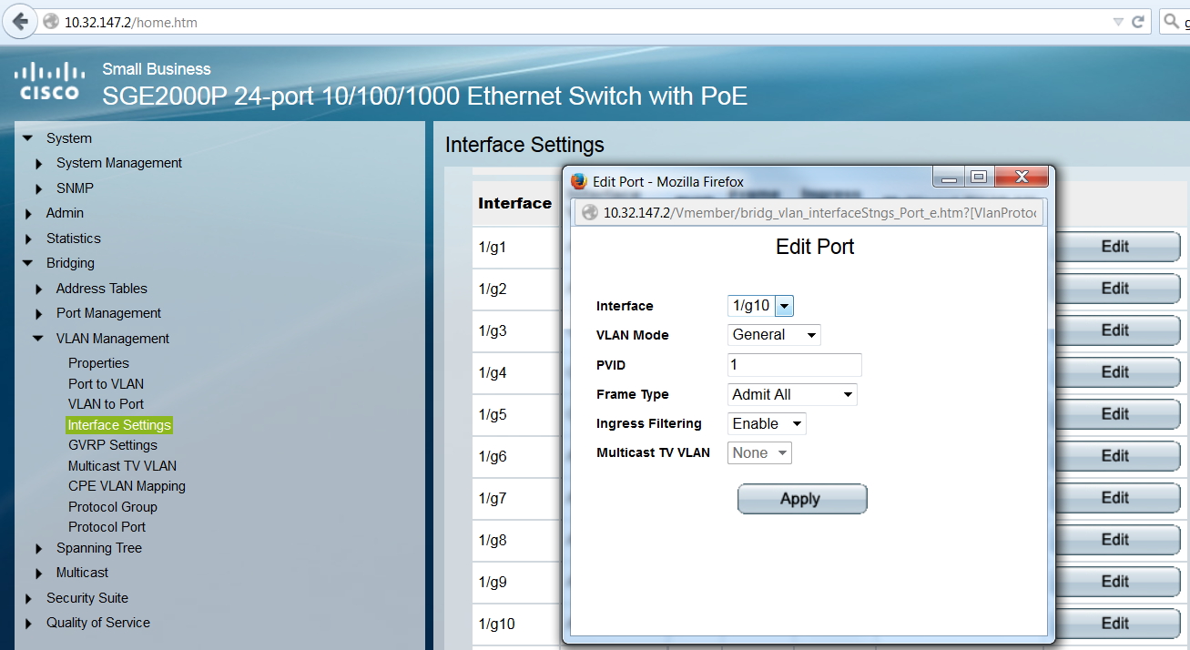
Set each of the SG300 Ports to type General with the Port VLAN ID (PVID) to Port 1. Type 'General' will allow the untagged PVID and tagged VLANs to operate on the same port.
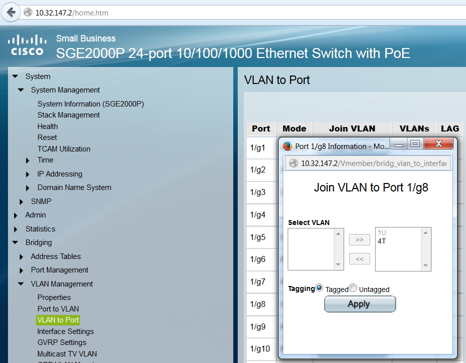
Port 8 is connected to the Guest WiFi Access Point and Port 10 is the uplink port to the router. Both of these ports need to be configured to accept tagged VLAN4 traffic.
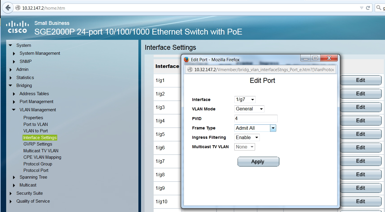
We have Port 7 of the switch connected to an Ethernet jack in the guest house. We want the guest to receive untagged VLAN4 traffic - so the guest will be in the 10.32.148.X network. So we set the PVID of Port 1/g7 to 4.
What's Next - Preparing Our Router to Support VLANs
Now that we have our managed switch ready to thoughtfully route VLAN traffic to devices on our Home Network and Guest Network, we need to install openwrt on our TPLink router so the router will support 802.1q VLANs.
Next article: Installing Openwrt on the TPLink TL-WR1043ND Router.
Articles in This Series:
- Guest Wifi Network - Part 1 - Device Selection
- Guest Wifi Network - Part 2 - Why VLANs
- Guest Wifi Network - Part 3 - Setting Up the TPLink TL-WA801N Access Points
- Guest Wifi Network - Part 4 - Setting Up the Cisco Linksys Sg300-10P Managed Switch
- Guest Wifi Network - Part 5 - Installing Openwrt on the TPLink TL-WR1043ND Router
- Guest Wifi Network - Part 6 - Setting Up the TPLink TL-WR1043ND Router