This article is one of a multi-part series on setting up a segregated Guest Network, including a guest WiFi network, within a Home Network. It is essentially an introduction to Virtual Local Area Networks ( VLAN), provides a simple use case for VLANs and gives a complete set of recommended hardware plus details the setup of that hardware.
The series of Guest Network articles progresses as follows:
We select a set of low cost hardware to meet our criteria of creating a Guest Network, including Guest WiFi, within our Home Network.
We set up the TPLink TL-WA801N WiFi Access points. This is a very simple process where configure each AP onto our Home Network and configure the AP's WiFi to operate on our separate Guest Network VLAN.
We set up our managed switch, a Cisco Linksys SG300-10P, to send Home Network traffic to only the Home Network devices and Guest Network traffic to only the Guest Network devices. And we show the special case of mapping the Guest Network Access Points onto both networks simultaneously.
We begin preparing our main router, a TPLink TL-WR1043ND, to create and manage the VLAN traffic for our Home Network and our Guest Network. Since the WR1043ND does not come with 802.1q VLAN support out of the box, this article is where we install openwrt on the WR1043ND.
In this final article of the series, Part 6, we configure openwrt of the TPLink TL-WR1043ND with the VLANs we need to create and maintain our separate Guest Network and Home Network.
VLANs to Be Used
VLAN1. The home network at 10.32.147.X. These devices are all our personal devices include laptops, desktops, phones, printers, etc.
VLAN2. On the TPLink WR-1043ND router, VLAN2 is the WAN port. This is connected to a cable modem in our case.
VLAN4. This is the guest network at 10.32.148.X.
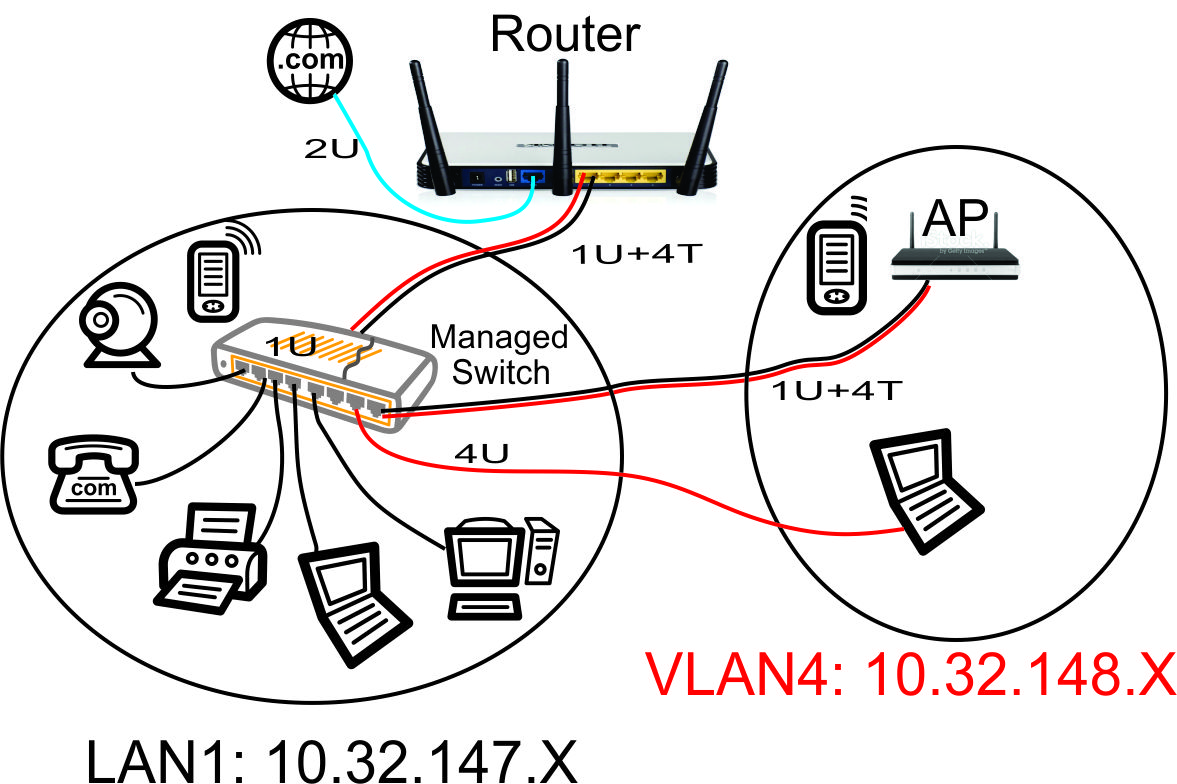
Guest Network Diagram
The above network diagram shows how we defined the ports on our Cisco Linksys SG-300-10P Power Over Ethernet (PoE) managed switch in a previous article.
Our guest WiFi Access Point, configured in a previous article in this series, is shown in the upper right hand corner. This Access Point will hand out WiFi IP addresses in the guest network range of 10.32.148.X. To make it easy to configure the Access Point from our home network, we put the AP's web configuration page on our home network with the 10.32.147.X range. This will prevent guests from being able to modify the AP settings.
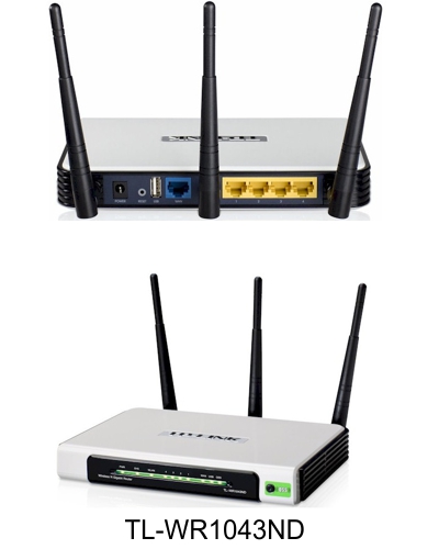
Version 1.X TPLink TL-WR1043ND Router
If you have the version 2.X hardware, it uses an Atheros AR8327N switch chip instead of the Realtek RTL8366rb that is used in the V1.X hardware. It appears from the documentation of openwrt ticket #12181 that the 'Barrier Breaker' V14.07 Stable image for V2.X hardware does NOT have the 802.1q VLAN support. If your VLANs do not work with V2.X hardware, please check the status of openwrt ticket #12181 and use the appropriate version of openwrt. So buying V1.X hardware might be easier 🙂
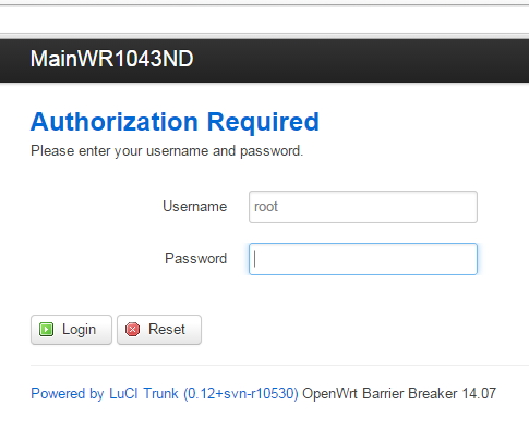
Login to Openwrt
Once the firmware upgrade is complete, you will see the front panel lamps on the WR1043ND light up with the SYS lamp on steady. Re-enter the IP address 192.168.1.1 in your browser.
WR1043ND Openwrt Login Page
The default user name is 'root' and there is no password at first login. Complete the login and create a new password, as prompted.
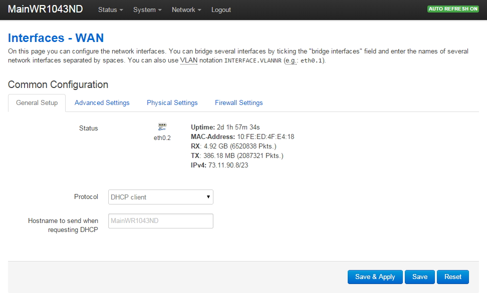
Setup WAN Interface in Openwrt
Go to Network->Interfaces. Click on WAN. Following is a shot of my WAN setup. It required no changes since my WR1043ND plugs into a cable modem that has its own DHCP server. So the WR1043ND is simply a DHCP client on its WAN port.
WR1043ND OpenWrt WAN Setup Page
Please note there is considerable documentation on the openwrt WR1043ND web page about the 'WAN Port Disable' bug. I DID NOT experience this problem, however I thought I did! My Comcast Docsis 3 cable modem is very picky about replacing the router connected to the cable modem: it will not allow a new device to be plugged in without repowering the cable modem. So once I connected the WR1043ND to the cable modem and cycled the power on the cable modem, the WR1043ND WAN port picked up an IP address from the cable modem and began working fine.
Verify your WAN port is connected before continuing: you should see the uptime increment in the above screen.
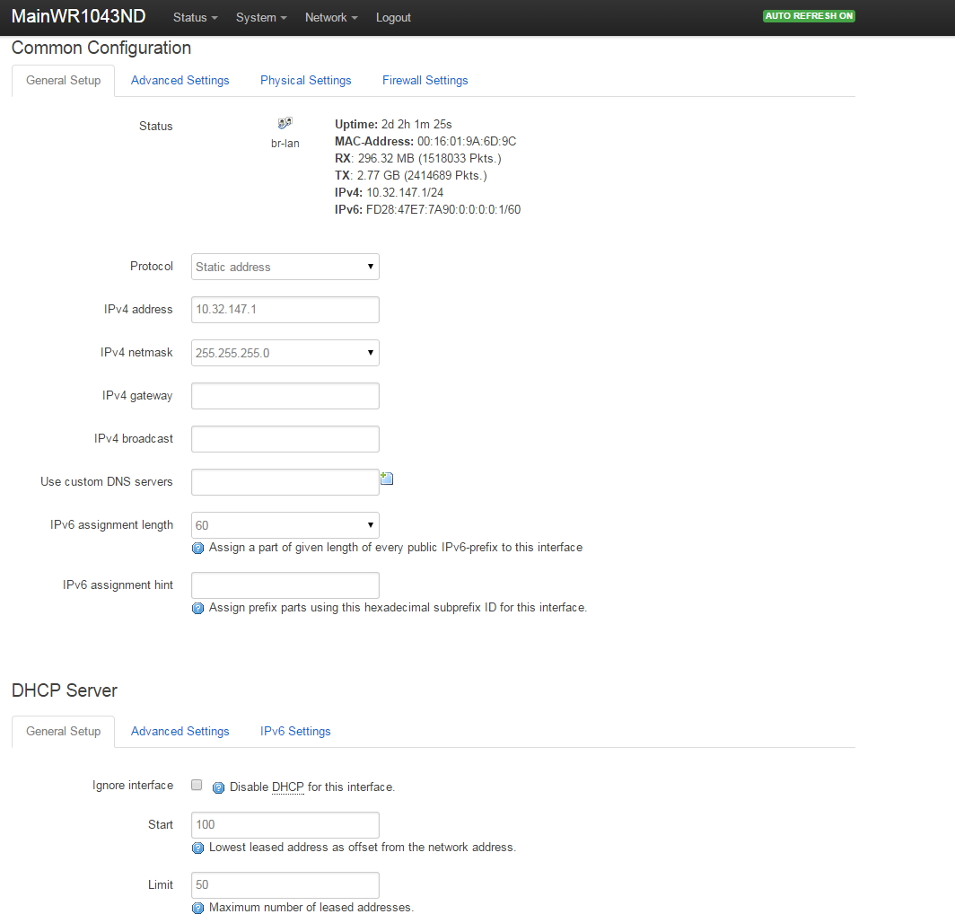
Setup LAN Interface in Openwrt
Go to Network->Interfaces. Click on LAN. Following is a shot of my LAN setup.
WR1043ND OpenWrt LAN Setup Page
Referring to the network diagram at the beginning of this article, we set up the LAN to have the router at 10.32.147.1, the mask to 255.255.255.0 (maximum 254 addresses on LAN), and the DHCP to provide addresses from 10.32.147.100 through 10.32.147.149 for our main home network devices.
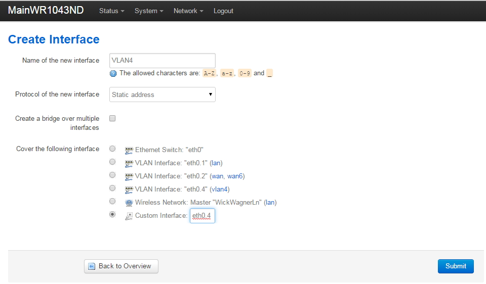
Setup VLAN4 Interface in Openwrt
Go to Network->Interfaces. Click on 'Add New Interface' and create a new VLAN named VLAN4 on eth0.4.
WR1043ND OpenWrt Network Interfaces 'Add New interface' VLAN Page
Your screen will not have the already existing VLAN Interface "etho.4" as shown above (the fourth radio button down in the 'Cover the following interface' list). You will click on 'Custom Interface' and enter 'eth0.4' to create the interface (as shown).
Note that we are NOT creating a bridge here (do not check the 'Create a bridge over multiple interfaces' checkbox): we want the VLAN4 guest network to be completely standalone.
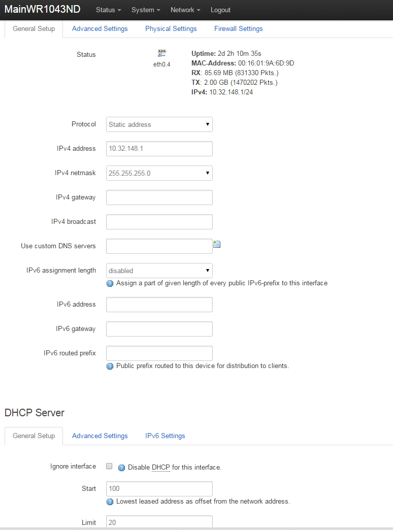
Setup of VLAN4 is very similar to the interface 'LAN'. Differences are:
Router address of VLAN4 is at 10.32.148.1. The LAN that we created earlier is at 10.32.147.1.
On VLAN4, I decided to hand out a maximum of 20 DHCP addresses on the guest network. The main home network on the LAN interface will generate up to 50 IP addresses with DHCP.
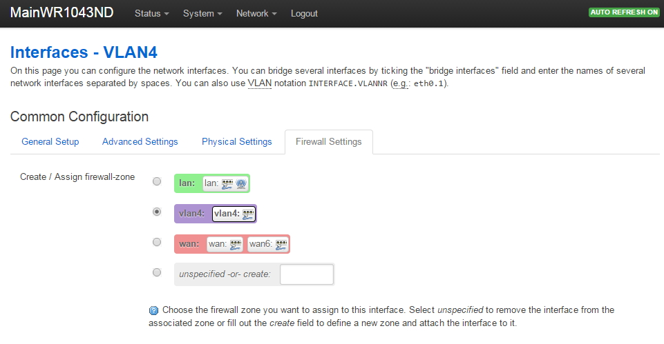
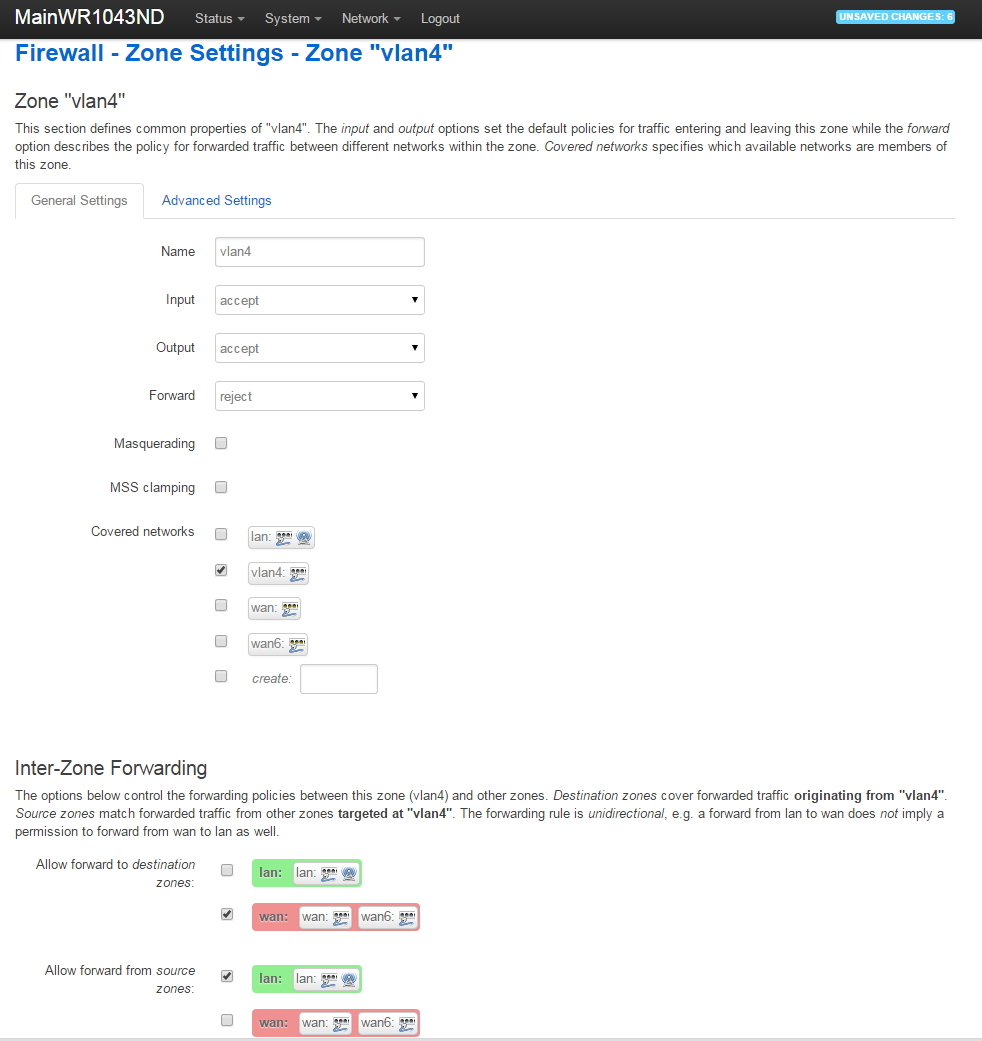
Under the Firewall Settings tab for VLAN4, we put VLAN4 in its own firewall zone that we create and name VLAN4. Under Firewall Settings, click on 'unspecified-or-create', enter 'vlan4', then press 'Save and Apply'. After doing that, your VLAN4 Firewall Settings will look like this:
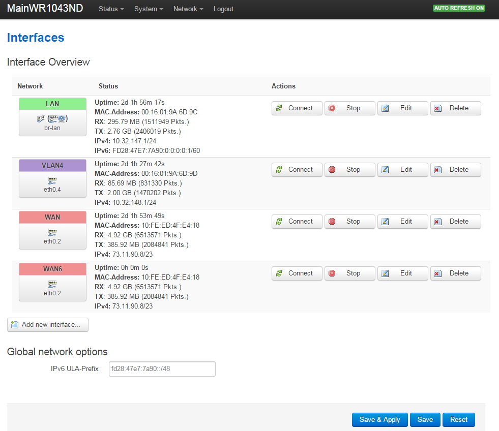
Your Network->Interfaces should now look like this:
WR1043ND OpenWrt VLAN Network Interfaces Page
Note I did manually set MAC addresses for the LAN and VLAN4 interfaces, otherwise the system uses the same MAC address for every interface. Seemed weird to me...
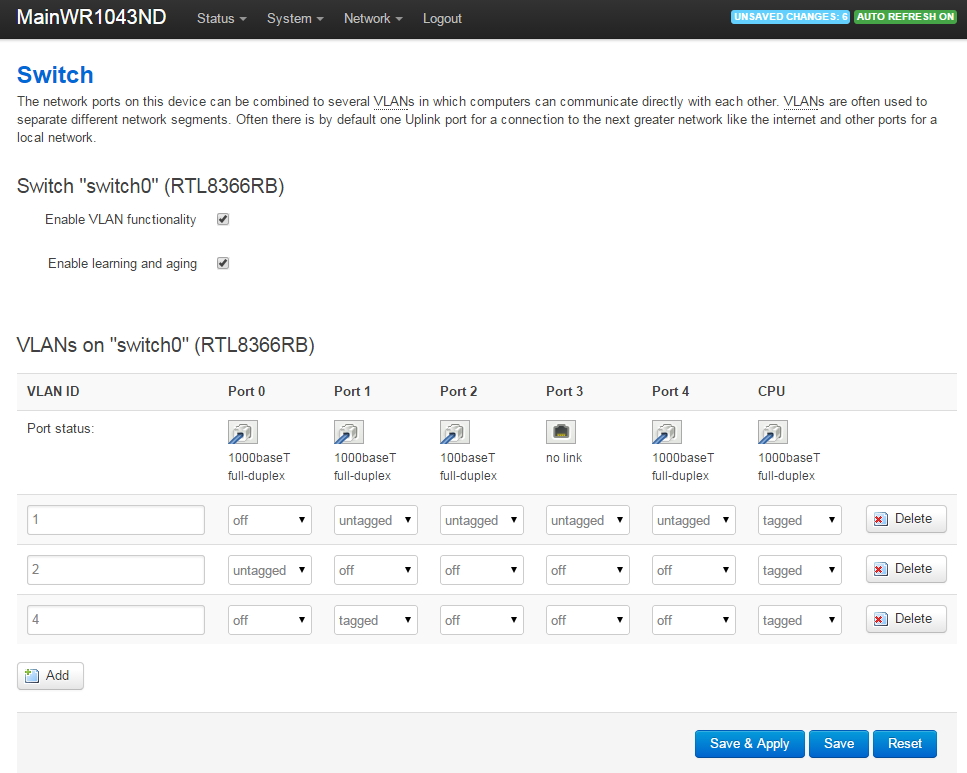
Start Sending VLAN4 Traffic to Managed Switch
Go to Network->Switch. Click on 'Add' and send the VLAN4 traffic out the router port that is connected to the Cisco Linksys Managed Switch. In my case, Port 1 of the router is connected to the Cisco Linksys managed switch. Be careful here: the port drawing seems backwards to me so I just disconnected the Ethernet cable to watch where traffic disappeared and used that as the correct port on the router.
WR1043ND OpenWrt VLAN Network Switch Page
Port 0 is the WAN port, Ports 1 through 4 are the LAN ports (the openwrt drawing doesn't match the router unless you look at it from the rear), and Port 5 is the CPU.
After pressing add, enter the VLAN ID '4', set Port 1 to transmit/receive 'tagged' traffic and be sure to also set the CPU to transmit/receive tagged traffic.
We now have tagged VLAN4 traffic going to the managed switch, but we can't ping anything yet because we need to set up the firewall rules for VLAN4.
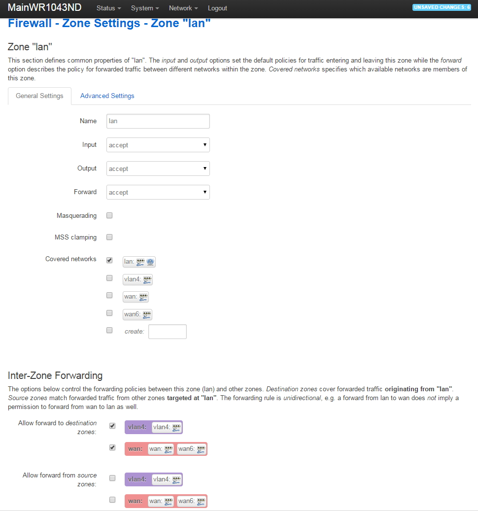
Configure VLAN4 Firewall Settings
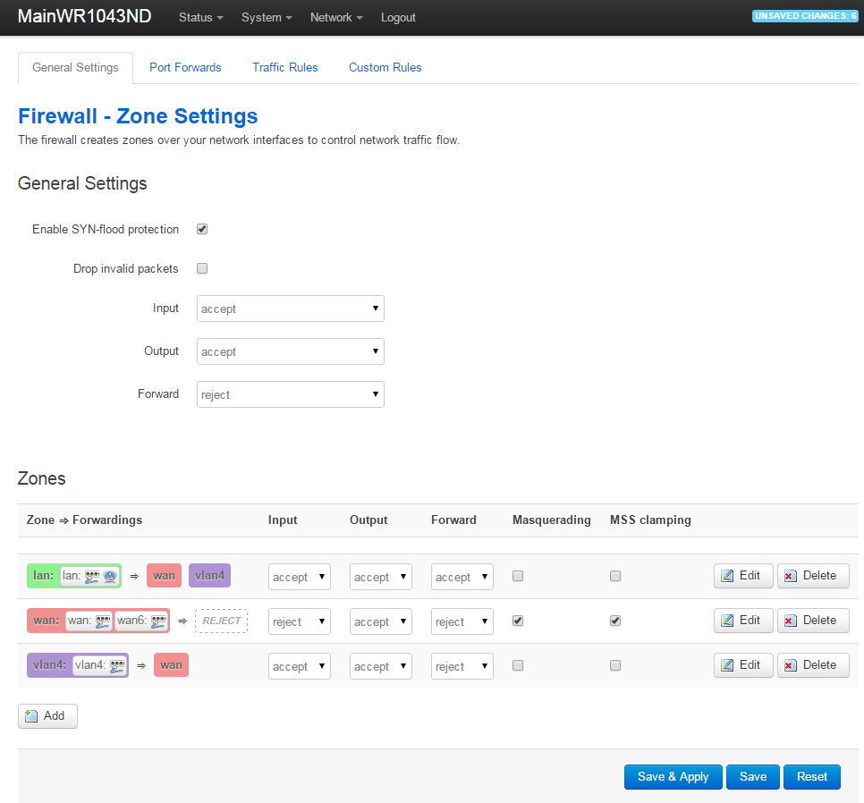
Go to Network->Firewall. You'll see that the firewall rule named vlan4 is currently set to 'Reject' and there is no traffic allowed from the LAN to VLAN4. We will modify the firewall settings so they end up looking like this:
WR1043ND OpenWrt VLAN Network Firewall Page
Under the Zones, click on the vlan4 edit button and make the following changes to allow vlan4 traffic out to the WAN (give vlan4 access to the Internet):
WR1043ND OpenWrt VLAN Network Firewall Zones Edit Page for New VLAN
After saving the vlan4 zone firewall settings, go back to Network->Firewall, go down to the lan zone, then click on the lan Edit button. Make the following changes to allow the lan to access devices on vlan4 (but not vice versa):
WR1043ND OpenWrt VLAN Network Firewall Zones Edit Page for LAN
Run in Circles, Scream and Shout
Would you believe we're done? Hooray!
You should now have a Guest Network that can connect to the Internet but is fully isolated from your main Home Network.
This article is one of a multi-part series on setting up a segregated Guest Network, including a guest WiFi network, within a Home Network. It is essentially an introduction to Virtual Local Area Networks ( VLAN), provides a simple use case for VLANs and gives a complete set of recommended hardware plus details the setup of that hardware.
The series of Guest Network articles progresses as follows:
We select a set of low cost hardware to meet our criteria of creating a Guest Network, including Guest WiFi, within our Home Network.
We set up the TPLink TL-WA801N WiFi Access points. This is a very simple process where configure each AP onto our Home Network and configure the AP's WiFi to operate on our separate Guest Network VLAN.
We set up our managed switch, a Cisco Linksys SG300-10P, to send Home Network traffic to only the Home Network devices and Guest Network traffic to only the Guest Network devices. And we show the special case of mapping the Guest Network Access Points onto both networks simultaneously.
We begin preparing our main router, a TPLink TL-WR1043ND, to create and manage the VLAN traffic for our Home Network and our Guest Network. Since the WR1043ND does not come with 802.1q VLAN support out of the box, this article is where we install openwrt on the WR1043ND.
In this article of the series, Part 5, we replace the stock TPLink firmware of the TL-WR1043ND router with a version of openwrt that is compiled specifically for this router. We need to use openwrt because it fully supports the 802.1q VLANs we will be using to create and maintain our separate Home Network and Guest Network.
Guest Network Diagram
Install Openwrt on the Router
The TPLink TL-WR1043ND WiFi Gigabit router does NOT support 802.1q VLANs with the standard TPLink firmware. We will replace the firmware with openwrt to get the 802.1q functionality.
Fortunately, there are firmware images readily available to easily add openwrt. Warning: you can 'brick' the router if you screw this up, making your life difficult. Be careful. No warranties.
Before powering up your WR1043ND, download the appropriate firmware image from the openwrt website using your existing Internet connection. I googled 'wr1043nd openwrt' and it brought me directly to the appropriate webpage. Download the Stable, Factory image for the version 1 hardware you purchased. My WR1043ND says it is version 1.11 on the label on the back of the WR1043ND, so I downloaded the V1.X, Stable, Factory image. Be very careful to download the proper image for your hardware version and existing software.
Version 1.X TPLink TL-WR1043ND Router
Following are the 2 stable versions of TPLink WR1043ND openwrt 'Barrier Breaker' firmware for the version 1.X WR1043ND hardware that we successfully used in February 2015:
If you have the version 2.X hardware, it uses an Atheros AR8327N switch chip instead of the Realtek RTL8366rb that is used in the V1.X hardware. It appears from the documentation of openwrt ticket #12181 that the 'Barrier Breaker' V14.07 Stable image does NOT have the 802.1q VLAN support so you will need to use a Trunk image (or build your own from source) instead of downloading the Stable image. So buying V1.X hardware might be easier 🙂
Download and save the appropriate firmware image (.bin) file, either from the selections above or get the needed image from the openwrt website. Be sure to pay attention to the location of the folder that you downloaded into since you'll need to get back to the same folder in a few moments (when you no longer have an Internet connection). You may need to rename the openwrt firmware image file to a shorter name: my router would not recognize the file until I shortened the name.
Now that you have downloaded the openwrt firmware to your laptop (quick check: do you remember which folder the file is in?), you will disconnect your laptop from your existing Internet-connected network and connect it to the new WR1043ND.
I recommend you power up your new WR1043ND, but do not plug it into any existing network. Unplug your Ethernet cable from your laptop (after you have previously downloaded the openwrt firmware), connect your laptop to a LAN port on the new standalone WR1043ND, run a Windows CMD shell to perform the command 'ipconfig /release' and 'ipconfig /renew' and your laptop should now have an IP address in the 192.168.1.X range that was generated by the WR1043ND.
An out-of-the-box WR1043ND will be at IP address 192.168.1.1 on its LAN with a login user name of 'admin' and a password of 'admin'. If you have modified any of these parameters, you'll need to respond appropriately.
Use your browser to login to 192.168.1.1, user: admin, password: admin.
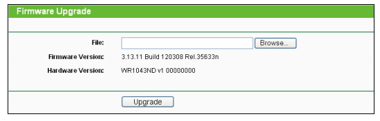
From the stock TPLink firmware, choose the menu 'System Tools->Firmware Upgrade':
WR1043ND TPLink Firmware Update Page
Browse to the openwrt firmware image you just downloaded, press the 'Upgrade' button in the above dialog box, and be patient. Wait for the WR1043ND to upload the firmware, write it to its flash RAM, and reboot: this can take a few minutes. Wait for it to complete.
Login to Openwrt
Once the firmware upgrade is complete, you will see the front panel lamps on the WR1043ND light up with the SYS lamp on steady. Re-enter the IP address 192.168.1.1 in your browser.
WR1043ND Openwrt Login Page
The default user name is 'root' and there is no password at first login. Complete the login and create a new password, as prompted.
Setup WAN Interface in Openwrt
Go to Network->Interfaces. Click on WAN. Following is a shot of my WAN setup. It required no changes since my WR1043ND plugs into a cable modem that has its own DHCP server. So the WR1043ND is simply a DHCP client on its WAN port.
WR1043ND WAN Setup Page
Please note there is considerable documentation on the openwrt WR1043ND web page about the 'WAN Port Disable' bug. I DID NOT experience the 'WAN Port Disable Bug', however I thought I did! My Comcast Docsis 3 cable modem is very picky about replacing the router connected to the cable modem: it will not allow a new device to be plugged in without repowering the cable modem. So once I connected the WR1043ND to the cable modem and cycled the power on the cable modem, the WR1043ND WAN port picked up an IP address from the cable modem and began working fine.
Verify your WAN port is connected before continuing: you should see the uptime increment in the above screen.
Setup LAN Interface in Openwrt
Go to Network->Interfaces. Click on LAN. Following is a shot of my LAN setup.
WR1043ND LAN Setup Page
Referring to the network diagram at the beginning of this article, we set up the LAN to have the router at 10.32.147.1, the mask to 255.255.255.0 (maximum 254 addresses on LAN), and the DHCP to provide addresses from 10.32.147.100 through 10.32.147.149 for our main home network devices.
What's Next - Configuring VLANs on the Router
Now that we have openwrt installed on our router, we can proceed to the final step in our series of articles where we setup the router for our 802.1q VLAN traffic.
This article is one of a multi-part series on setting up a segregated Guest Network, including a guest WiFi network, within a Home Network. It is essentially an introduction to Virtual Local Area Networks ( VLAN), provides a simple use case for VLANs and gives a complete set of recommended hardware plus details the setup of that hardware.
The series of Guest Network articles progresses as follows:
We select a set of low cost hardware to meet our criteria of creating a Guest Network, including Guest WiFi, within our Home Network.
We set up the TPLink TL-WA801N WiFi Access points. This is a very simple process where configure each AP onto our Home Network and configure the AP's WiFi to operate on our separate Guest Network VLAN.
We set up our managed switch, a Cisco Linksys SG300-10P, to send Home Network traffic to only the Home Network devices and Guest Network traffic to only the Guest Network devices. And we show the special case of mapping the Guest Network Access Points onto both networks simultaneously.
We begin preparing our main router, a TPLink TL-WR1043ND, to create and manage the VLAN traffic for our Home Network and our Guest Network. Since the WR1043ND does not come with 802.1q VLAN support out of the box, this article is where we install openwrt on the WR1043ND.
In this article of the series, Part 4, we'll configure the Cisco Linksys SG300-10P managed switch to thoughtfully send traffic to devices on our Home Network and our Guest Network.
VLANs to Be Used
Our system will be using the following VLANs:
VLAN1. The home network at 10.32.147.X. These devices are all our personal devices include laptops, desktops, phones, printers, etc.
VLAN2. On the TPLink WR-1043ND router, VLAN2 is the WAN port. This is connected to a cable modem in our case.
VLAN4. This is the guest network at 10.32.148.X.
Guest Network Diagram
The above network diagram shows how we will be defining the ports on our Cisco Linksys SG-300-10P Power Over Ethernet (PoE) managed switch.
Our guest WiFi Access Point is shown in the upper right hand corner. This Access Point will hand out WiFi IP addresses in the guest network range of 10.32.148.X. To make it easy to configure the Access Point from our home network, we will put the AP's web configuration page on our home network with the 10.32.147.X range. This will prevent guests from being able to modify the AP settings.
We will also create a port on the managed switch that will allow a guest to plug into a wired Ethernet connection and automatically be connected to the VLAN4 10.32.148.X guest network.
Cisco Linksys SG300-10P Managed 10 Port Gigabit Switch with PoE
Set Up the Managed Ethernet Switch
The Cisco Linksys SG-300P managed Ethernet switch will be minimally configured as follows:
Set its web configuration IP address at a fixed address on the 10.32.147.X primary home network.
Configure the port that is connected to the router to accept untagged VLAN1 traffic and tagged VLAN4 traffic.
Configure the port that is connected to the guest access point to accept untagged VLAN1 traffic and tagged VLAN4 traffic.
Configure the port that is connected to the guest Ethernet jack to accept untagged VLAN4 traffic only.
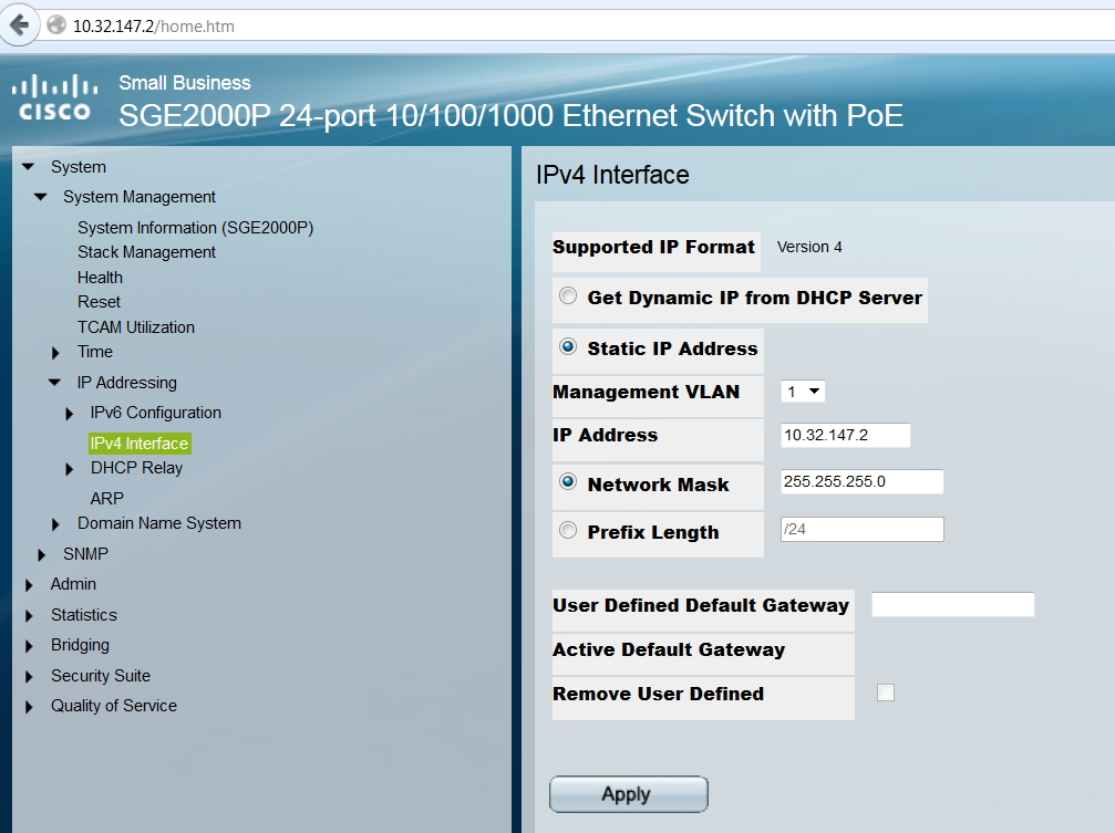
Please note: for some reason,I cannot use Google Chrome (my preferred browser) to access the SG-300P configuration web page. I use Firefox instead.Hmm....
Setting the IP Address of the SG300P on Our Main Home Network
Setting SG300 Ports to Type General
Set each of the SG300 Ports to type General with the Port VLAN ID (PVID) to Port 1. Type 'General' will allow the untagged PVID and tagged VLANs to operate on the same port.
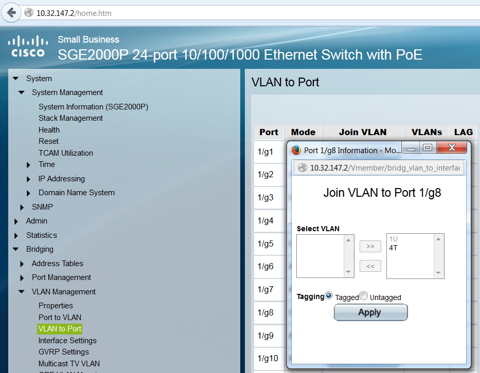
Setting SG300 Port 8 to Accept Tagged VLAN4 Traffic
Port 8 is connected to the Guest WiFi Access Point and Port 10 is the uplink port to the router. Both of these ports need to be configured to accept tagged VLAN4 traffic.
Setting SG300 Guest Network Ethernet Port to Untagged VLAN4
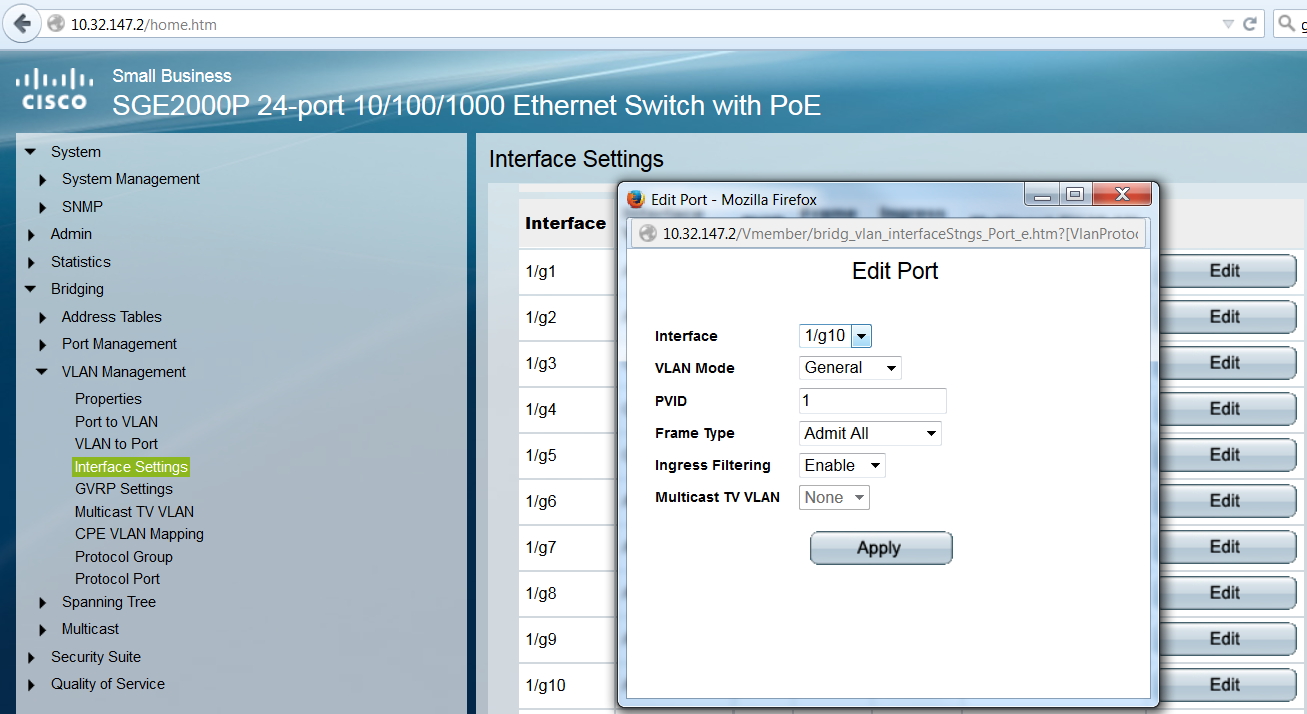
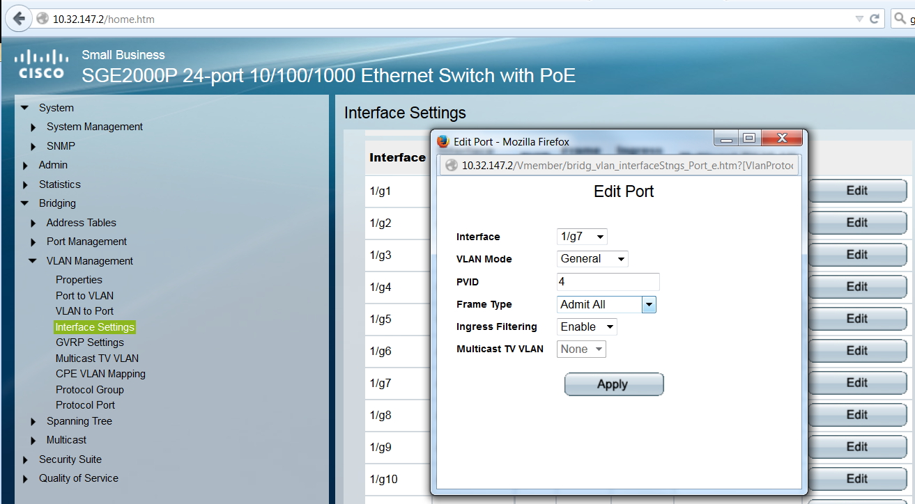
We have Port 7 of the switch connected to an Ethernet jack in the guest house. We want the guest to receive untagged VLAN4 traffic - so the guest will be in the 10.32.148.X network. So we set the PVID of Port 1/g7 to 4.
What's Next - Preparing Our Router to Support VLANs
Now that we have our managed switch ready to thoughtfully route VLAN traffic to devices on our Home Network and Guest Network, we need to install openwrt on our TPLink router so the router will support 802.1q VLANs.
This article is one of a multi-part series on setting up a segregated Guest Network, including a guest WiFi network, within a Home Network. It is essentially an introduction to Virtual Local Area Networks ( VLAN), provides a simple use case for VLANs and gives a complete set of recommended hardware plus details the setup of that hardware.
The series of Guest Network articles progresses as follows:
We select a set of low cost hardware to meet our criteria of creating a Guest Network, including Guest WiFi, within our Home Network.
We set up the TPLink TL-WA801N WiFi Access points. This is a very simple process where configure each AP onto our Home Network and configure the AP's WiFi to operate on our separate Guest Network VLAN.
We set up our managed switch, a Cisco Linksys SG300-10P, to send Home Network traffic to only the Home Network devices and Guest Network traffic to only the Guest Network devices. And we show the special case of mapping the Guest Network Access Points onto both networks simultaneously.
We begin preparing our main router, a TPLink TL-WR1043ND, to create and manage the VLAN traffic for our Home Network and our Guest Network. Since the WR1043ND does not come with 802.1q VLAN support out of the box, this article is where we install openwrt on the WR1043ND.
In this article of the series, Part 3, we configure the TPLink TL-WA801N Access Points to create a WiFi Guest Network. This is an interesting VLAN case since we want to put the AP web configuration page on our Home Network, but have the Guest WiFi run from our Guest Network. This approach discourages our guests from attempting to mess with our Access Points.
Why We Selected the TPLink TL-WA801ND
Update: I tried using these TL-WA801ND Access Points for about a year and made a point of upgrading the firmware whenever TpLink released new versions. But these were NOT reliable: each of them would crash and lock up every few days to few weeks. This was totally unacceptable for our Bed & Breakfast since these access points seemed to sense when I was out of town, not available to bring them back to life. I needed RELIABLE hardware and these did not fit the bill.
I have since replaced these TL-WA801ND AP's with multiple ZyXel NWA-1123 AP's and there is a night and day difference in reliability. Not one crash in over two years time with the ZyXel Access Points. The ZyXel AP's also easily support the VLAN configurations and (true) PoE described throughout these documents. The Zyxel AP's include both 2.4GHz and 5 GHz radios: they support 802.11 a/b/g/n/ac instead of just 2.4GHz b/g/n. Definitely more expensive than the TpLink AP's, around $100 each instead of $55 each ($35 for TpLink AP plus $20 for TpLink PoE Splitter), but I need equipment that works!
This TL-WA801ND Access Point has the following features we are using:
They support multiple WiFi SSID's, each on their own VLAN, so we can easily add a Guest WiFi Network.
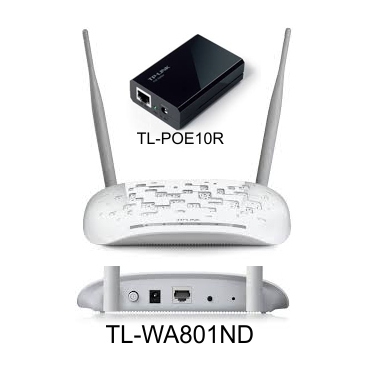
They offer passive PoE which allows us to power the Access Point through our Ethernet wiring instead of having to find a nearby 110VAC outlet. This requires a PoE switch and the TPLink TL-POE10R that converts the 48V PoE to the 9V required by the WA801ND. If you get an idea to use the TL-POE10R to power a different AP, be sure the AP does not draw more power (amps) than the TL-POE10R will provide.
They allow us to put the configuration address of the AP on our Home Network while the Guest Network is on a different VLAN (this is essentially just a side effect of the multi-SSID feature).
They are inexpensive.
TPLink TL-WA801ND VLAN-Capable Access Point with TL-POE10R PoE PoE Splitter
VLANs to Be Used
We'll be using two VLANs simultaneously on our Guest Access Points:
VLAN1. The Home Network at 10.32.147.X. We'll statically map the AP's configuration web page to one of our available Home Network IP addresses.
VLAN4. This is the guest network at 10.32.148.X. The WiFi access point will use the Guest Network DHCP to hand out Guest Network IP addresses (10.32.148.X) to Guest WiFi client devices.
Guest Network Diagram
Set Up the Guest Access Point
The TPLink TL-WA801N Access Point comes out of the box ready to support VLANs for the WiFi.
To configure the TL-WA801N:
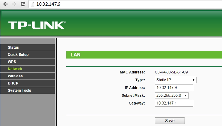
Set its web configuration IP address at a fixed address on the 10.32.147.X primary home network.
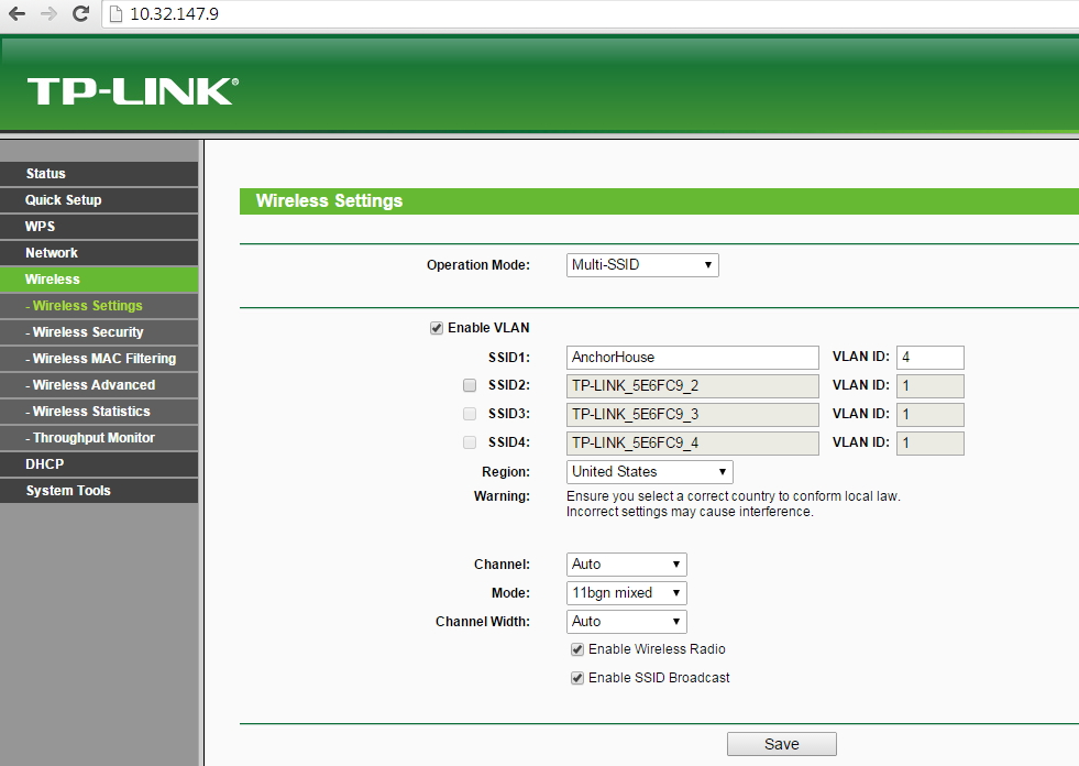
Configure a WiFi SSID on VLAN4.
Setting the IP Address of the WA801 on Our Main Home Network
When we add a second Guest Network Access Point, we'll give it a unique IP address (we will not re-use the 10.32.147.9 address above). For example, our second AP will instead use 10.32.147.10.
Setting the WA801 for Multi-SSID VLAN WiFi on VLAN4
When we install a second Guest Network Access Point, it will use the exact same WiFi settings as above. This will allow our guests to enter the WiFi password just once on their client device, then travel through our home, relying on their client device to select the strongest WiFi radio signal.
What's Next - Configuring the Managed Switch
Now that we have our Guest Access Points ready to accept traffic on VLAN4, we will set up our managed switch to thoughtfully route VLAN traffic to devices on our Home Network and Guest Network.
This article is one of a multi-part series on setting up a segregated Guest Network, including a guest WiFi network, within a Home Network. It is essentially an introduction to Virtual Local Area Networks ( VLAN), provides a simple use case for VLANs and gives a complete set of recommended hardware plus details the setup of that hardware.
The series of Guest Network articles progresses as follows:
We select a set of low cost hardware to meet our criteria of creating a Guest Network, including Guest WiFi, within our Home Network.
We set up the TPLink TL-WA801N WiFi Access points. This is a very simple process where configure each AP onto our Home Network and configure the AP's WiFi to operate on our separate Guest Network VLAN.
We set up our managed switch, a Cisco Linksys SG300-10P, to send Home Network traffic to only the Home Network devices and Guest Network traffic to only the Guest Network devices. And we show the special case of mapping the Guest Network Access Points onto both networks simultaneously.
We begin preparing our main router, a TPLink TL-WR1043ND, to create and manage the VLAN traffic for our Home Network and our Guest Network. Since the WR1043ND does not come with 802.1q VLAN support out of the box, this article is where we install openwrt on the WR1043ND.
In this article of the series, Part 2, we discuss the principles and VLANs that we will be using to create our Guest Network. We'll use simple network diagrams to illustrate concepts, clarify our approach, and offer alternatives.
Review - What is a LAN
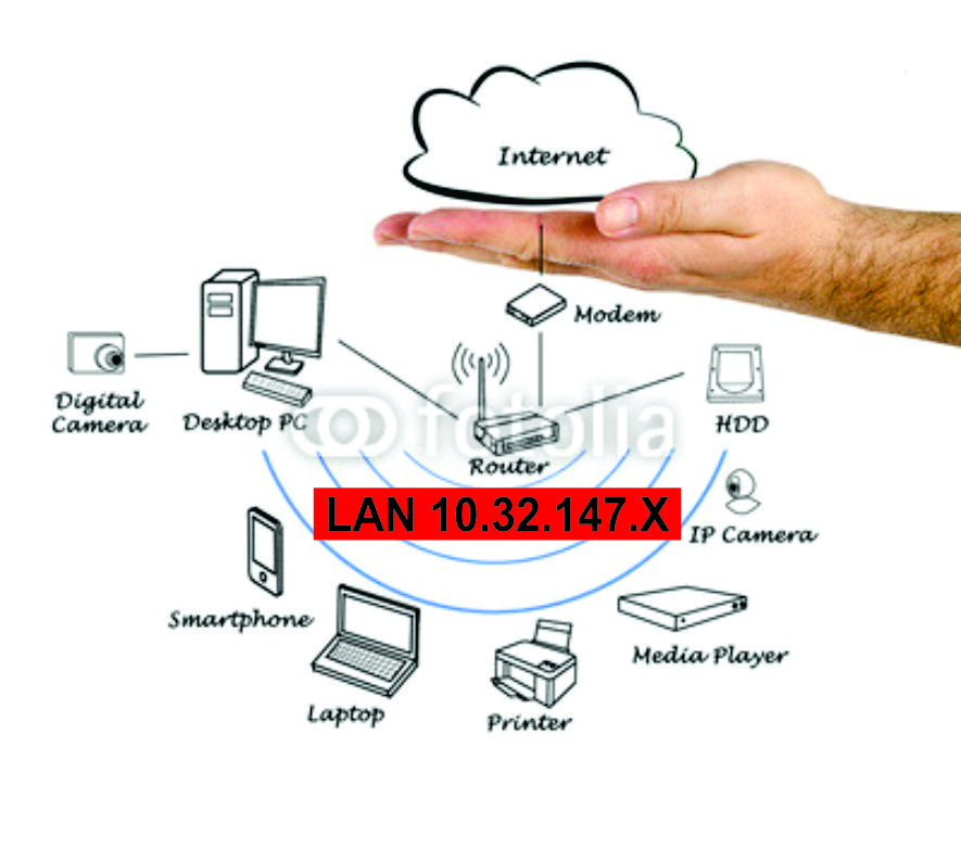
Before we jump into a discussion about VLANs, let's review what a LAN is: a number of Ethernet or WiFi devices all connected together that can talk to each other. They share a 'broadcast domain' to allow the devices to know about each other and cooperate. Here is a picture of a simple LAN: all the devices are in the same IP address range from 10.32.147.1 through 10.32.147.254.
All Devices on a Single LAN
Basics of a Single LAN
In the above example, we would define a LAN with the following characteristics:
The router's IP address is 10.32.147.1. It is the 'gateway' that all our devices go to whenever they need to get out to the Internet.
The mask for this LAN is 255.255.255.0: there can be up to 254 devices on this LAN.
The router's DHCP server hands out IP addresses to each device as it connects to the network. For example, we may have set up DHCP to hand out an address in the range from 10.32.147.100 through 10.32.147.150 whenever a new device is plugged into the LAN (or connected via WiFi).
The router passes the DNS addresses to the devices on the network. The Domain Name Service is the system that associates a URL name (www.alduras.com) with an IP address. All communications occur using IP addresses rather than names.
When a new device (PC, laptop, phone, etc.) connects to our LAN, it therefore gets the following information from the router:
IP Address. The device's IP address, for example 10.32.147.100. The router's DHCP server generates this local IP address.
Mask. The device's mask. In our example, this would always be 255.255.255.0, meaning this LAN can support up to 254 devices.
Gateway. The gateway address to be used by the device. In our example, this is the router's address 10.32.147.1. The device will therefore go to the gateway any time it needs information about devices outside our LAN addresses (for example, for all Internet access).
DHCP. The address of the DHCP server used to request the device's IP address. In a small network, this is virtually always the router's IP address, or 10.32.147.1 in our example.
DNS. The address of DNS servers to query when trying to resolve a name to an IP address.
Approach #1 - Adding a Guest Network Using Two Physical LANs
In the above single LAN example, all our devices are in the same network: all the devices communicate with each other by virtue of being within the address range of 10.32.147.1 through 10.32.147.255. The highest address, 10.32.147.255 is the multicast address: the address that any device can use to broadcast a message to all devices within our LAN. Multicast never goes outside a LAN: it stays within the local network only.
This single LAN is fine if we trust every device equally and we don't have any need to throttle service to any particular device. This approach is quite sufficient for most home networks.
But what happens if we have guests in our home? Do we want them to have access to the files and computers on our LAN? Or do we want our guests to have their own private LAN to ensure security of our files and computers, but still give our guests access to the Internet?
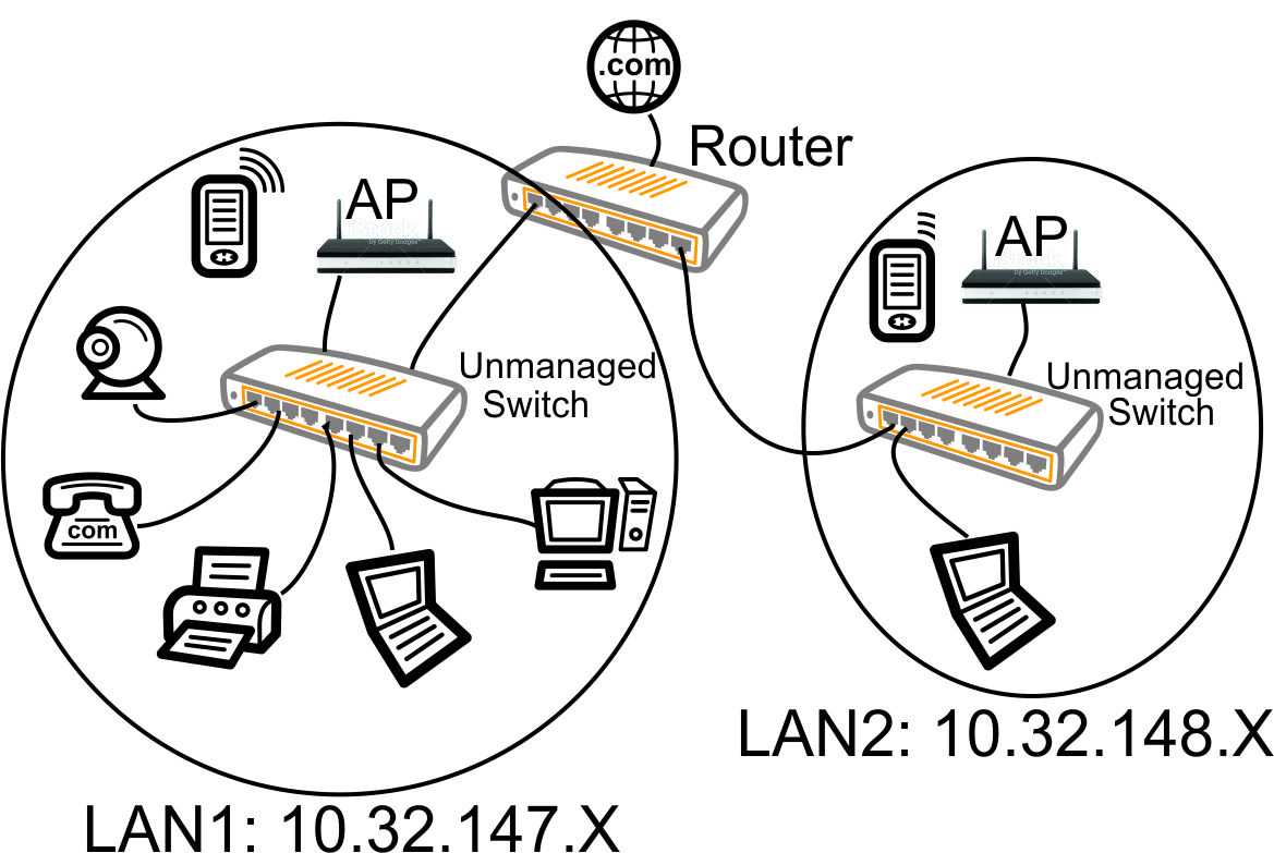
Before VLANs, the simplest method to create a second LAN would be to buy a second switch, buy a second WiFi access point, and run some wires to handle just LAN #2. We would add all the devices and wires to create a new LAN (the 10.32.148.X LAN) as shown in the following diagram. Note that each LAN has a unique IP range: this a requirement of separate LANs so the router knows which LAN is to be used (how to route the packets).
Two Physically Separate LANs. Guest Devices are Separated Onto a Physically Separate LAN (10.32.148.X)
Approach #2 - Adding a Guest Network Using One Physical LAN With Two Virtual LANs - Unmanaged Switch
However, adding a second physical LAN is expensive and inefficient. Why buy the second unmanaged switch and run new wires (all that equipment on the right in the above diagram)? How about we just use all our existing wiring?
The concepts are still the same with our VLAN instead of our physical LAN. Each VLAN is its own world with its own unique set of IP addresses, otherwise the router does not know where to route packets.
In this approach (and all subsequent approaches), we still have only one Ethernet wire - one physical LAN - but now we essentially split that wire into two virtual wires, or Virtual LANs:
VLAN1 - 10.32.147.x for our personal traffic
VLAN2 - 10.32.148.x for our guest traffic
If we have a VLAN aware router, we simply ask it to put the VLAN1 traffic AND the VLAN2 traffic out on the same port of the router. There are two ways we can do this:
We can output the VLAN1 traffic 'untagged' and the VLAN2 traffic 'tagged'. The advantage here is all the receiving devices of VLAN1 traffic do NOT have to be be VLAN aware: they will simply ignore the VLAN2 traffic.
We can output BOTH the VLAN1 and LAN2 traffic as 'tagged' VLANs. Pandomonium ensues. Nothing talks because now every device has to be VLAN aware: every device has to be able to dissect the special VLAN traffic and pull it out of the packets. The packets are reaching the devices in this scenario, but the devices don't know what to do with the VLAN packets.
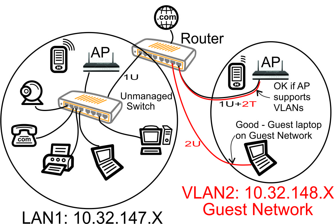
VLAN with Unmanaged Switch - Guest Laptop on Home Network
In the above diagram, each Ethernet cable is carrying both the VLAN1 traffic (the black VLAN1 untagged '1U' traffic) and the VLAN2 guest traffic (the red VLAN2 '2T' tagged traffic). When you see a red 'wire' alongside a black 'wire' above, it is NOT two different wires, but is instead a depiction of a VLAN connection with two (or more) sets of VLAN traffic traveling down the same Ethernet wire.
When we configure the router to send multiple VLAN traffic over an Ethernet connection and use an unmanaged switch, the VLAN1 and VLAN2 traffic is reaching every device, as shown above.
There are some problems with using the unmanaged switch in the above diagram:
The Guest Laptop will automatically connect to the Main Home Network, not the Guest Network. The VLAN1 (Main Home Network) traffic is the untagged traffic so the Ethernet of the laptop will use that traffic by default. Many laptops do have a provision to connect to a tagged VLAN by editing the network device hardware settings, but requiring your guests to modify their laptop settings just so they are not using your main home network is impractical.
The VLAN2 (Guest Network) traffic is needlessly being transmitted to all devices, not just the devices that need to access the Guest Network.
Tagged vs. Untagged VLANs
In our diagram above, we introduced the concept of tagged and untagged VLANs.
An 'untagged' packet is just a standard Ethernet packet: every device on the network will look at the packet and determine whether they should receive the packet. In our diagrams here, notice we always have a 'U' (untagged) wire going to every device: that is the untagged VLAN that every device knows how to handle.
A 'tagged' packet is essentially a hidden packet: every device on the network will ignore the tagged packet unless they are specifically looking for that exact VLAN tag number in the tagged packet. For a device to handle 'tagged' packets, that device must be explicitly configured to look for tagged packets . For example, if you want your PC to react to a tagged VLAN, you will need to set up the PC's Ethernet 'card' to look at only the traffic for a particular tagged VLAN number. In our diagrams here, notice we sometimes have a 'T' (tagged) virtual wire running alongside our physical 'U' (untagged) wire: we 'cheated' and created a second virtual Ethernet wire using our tagged VLAN.
In a nutshell: 'untagged' traffic just works without any special setup, but tagged traffic is that second (or more) Ethernet Virtual LAN that is ignored unless the receiving device is specifically looking for those tagged Ethernet frames.
You can only have one untagged VLAN on a port, however you can have many tagged VLANS on a port. If you try to put multiple untagged LANs on a port, it does not work.
Approach #3 - Adding a Guest Network using VLANs - Unmanaged Switch, Improved
With a bit of rewiring, we can utilize the unmanaged switch and the extra ports on the router to fix our problems with our prior approach. This change will work if we can physically move wires.
VLAN with Unmanaged Switch - Guest Laptop on Guest Network, No Guest Traffic on Home Network
With a couple wiring changes (connecting the AP and guest laptop directly to ports on the 802.1q VLAN capable router), we have dramatically improved our network.
All the devices on our main home network are receiving/transmitting only the VLAN1 10.32.147.X traffic. In VLAN parlance, we have placed VLAN1 untagged traffic (1U in above diagram) on the left port of the router.
The guest laptop is receiving/transmitting only the Guest Network 10.32.148.X traffic. In VLAN parlance, we have placed VLAN2 untagged traffic (2U in above diagram) on the port of the router that is second from the right.
The guest Access Point is managed from a home network IP address, but the WiFi is on the Guest Network. In VLAN parlance, we have placed both VLAN1 untagged traffic and VLAN2 tagged traffic (1U + 2T in above diagram) on the right port of the router.
We have accomplished our goal to separate the Home Network and Guest Network by using an 802.1q compliant router and performing a bit of knowledgeable rewiring.
Approach #4 - Adding a Guest Network using VLANs - Managed Switch
Although we accomplished our goal to separate out our Guest Network in the above scenario, we can make some notable improvements by replacing our unmanaged switch with an 802.1q compliant managed switch that has the ability to simultaneously map untagged and tagged traffic to any port (such as the Cisco Linksys SG300P).
Some of the advantages of upgrading to a managed switch:
Complete flexibility of which VLAN traffic goes out on which port. We can map any VLAN tagged and/or untagged to any port. This ensures security and reduces unnecessary traffic: each device receives only the VLAN traffic appropriate for the device.
We don't need to rewire anything like we did in the above scenario. The switch can receive all VLAN traffic from the router, then the managed switch can flexibly route traffic uniquely to each switch port as needed.
We can place our Ethernet wiring in one physical location and not have to worry how our network may need to be rewired based on our changing needs. For example, when rewiring my house (or business), I simply ran every Ethernet wire to one closet and put a large managed switch in that closet.
With the low cost of managed switches today, there is no compelling financial reason to buy an unmanaged switch. Managed gigabit switches are readily available for under $100.
So lets make a change and replace the Ethernet switch with a managed Ethernet switch. Now our VLAN based network can be cleaned up by configuring the managed switch to only pass traffic through the switch ports that make sense for our devices.
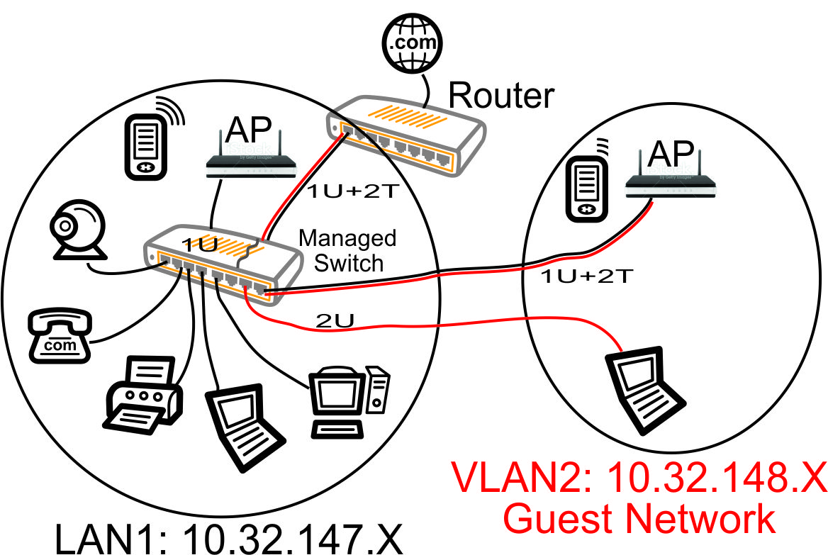
VLAN with Managed Switch
In the above diagram, red is VLAN2 traffic across our Ethernet wires, black is VLAN1 traffic, the 'U' means 'untagged' VLAN traffic and the 'T' means tagged VLAN traffic.
Our managed switch basically lets us 'carve up' the switch into a bunch of separate switches. We can overlap untagged and tagged traffic on each port of the switch in any manner we please.
Lets take a look at how we configured our managed switch above:
Ports 1-6 (the left ports) are configured to pass the LAN1 traffic untagged to all the devices connected to the 10.32.147.x network. The VLAN2 traffic does not appear on any of those devices.
Port 7 (second from right) is configured to take the tagged VLAN2 traffic from the router, strip off the tags, and send VLAN2 traffic untagged out port 7. So this makes it real easy to configure the laptop connected to port 7: it is just a normal Ethernet configuration that does not have to be VLAN aware. The laptop is on our guest 10.32.148.x network and cannot access any files or computers on the 10.32.147.x network (assuming the router's firewall is configured to prevent bridging). So now we can safely host a guest laptop without worrying about that laptop affecting our personal home machines. And the guest just plugs in to the Ethernet, lets DHCP hand out an address in a normal fashion, and enjoys high speed Internet access.
Port 8 (rightmost) is configured to pass the VLAN1 traffic untagged and the VLAN2 traffic tagged to the guest access point. That lets us put the configuration web page of the AP at one of our 10.32.147.x VLAN1 addresses, but puts the WiFi on our 10.32.148.x VLAN2 guest network. So we can manage the AP from our home computers, but the guests only get into the guest WiFi network. This requires an AP that supports SSID to VLAN mapping, such as the TPLINK TL-WA801ND Access Point.
The uplink port of the managed switch (shown at the rear of the switch in the diagram above) receives VLAN1 traffic untagged and VLAN2 traffic tagged. All traffic is passing over this trunk port between the switch and the router.
802.1Q - Router Required Feature for VLANs
When purchasing a router, you'll need one that supports 802.1Q VLANs in order to set up your segregated guest network. This is a function of the model of switch chip on your router: not all switch chips support the simultaneous tagged and untagged VLANs as we have shown in the above drawings (when there are red and black side-by-side virtual wires in the above diagrams).
802.1Q Trunking for Guest Network
If you decide to install a managed switch (approach #4 above), it will also need to support 802.1Q VLANs. I highly recommend a managed switch since it makes it so easy to 'carve up' your network into exactly what you may need, regardless of location or wiring. If all you're doing is setting up some WiFi access points on their own guest network (not setting up any wired Ethernet separate networks), then the managed switch is of less importance.
When you look at the switch chip features of your router and managed switch, you will see the following terminology related to VLAN port configuration:
Access Ports. These are ports that input and output ONLY untagged VLANs. They will NOT work for our guest network since they essentially do not support VLANs.
Trunk Ports. These are ports that can output one untagged VLAN (the 'native' VLAN which us usually VLAN1) and any number of tagged VLANs. For our guest network using VLANs, it is sufficient to use Trunk Ports.
General Ports (Hybrid Ports). These are ports that can map any tagged or untagged port to any other tagged or untagged port. In complex configurations, this flexible mapping can be used to speed up VLAN to VLAN switching by doing the switching at 'wire speeds', however there is no need for this capability in any of our guest network setups. Our guest network setups are careful to configure firewall rules between networks, so the router CPU must get involved, and therefore these 'wire speed' capabilities are of little use in our routers.
Some brands/versions of router Software will refer to Trunk Ports and mean ports that can output ONLY tagged VLANs: they don't support the one untagged native VLAN simultaneously on that Trunk port. Openwrt Version 18 seems to do a very good job of supporting simultaneous tagged/untagged VLANs on an 802.11Q Trunk port on many router models (if the switch chip supports it), but you will want to verify that capability before beating your head against the wall trying to get VLANs to work on your router.
If you refer to any of the Learning Articles here on this website (alduras.com) for routers I have set up with openwrt, they each support 802.1Q trunking.
When purchasing your router, it seems to be much too difficult to determine if they are truly 802.1Q capable. It seems to take a lot of careful and time-consuming searching. Do be diligent to search for that 802.1Q feature when you purchase your guest network router.
What's Next - Configuring the AP, Router & Switch
So now we have a nice, secure guest network together with a separate private home network. We'll configure the rules in the router firewall to keep VLAN1 and VLAN2 separate (however, maybe we'll allow VLAN1 to access VLAN2, but not vice versa).
Now that we understand the basic concepts of how we want to use VLANs and the managed switch to create our separate networks, let's go on to the next part in our series where we configure our Access Points.
We run a small Bed and Breakfast out of our house - or actually a couple vacation rental Suites since we don't offer the breakfast part of the B & B. I'm no cook :-), just a techno-geek who has thoroughly enjoyed meeting the friendly guests that have stayed in our home.
When we show our guests around, 100% of them have asked 'What is the WiFi password?' Every group of guests, of every age, has asked this question. No kidding: 100%. As an aside, our vacation rentals don't have phones: we rely on guest cell phones. So far, not one comment or question about the lack of phones. Its fair to say the world is now mobile - at all ages.
So figuring out a way to set up a guest WiFi network is de-rigueur for a vacation rental host in today's world.
My first attempt at setting up a guest WiFi network was easy and inexpensive. I ran Cat5E wires to each level of the house, put an Access Point at each level, and installed a switch to feed wired Ethernet to each Access point. I plugged those into my router and had a functional house-wide Wifi network in no time.
About This Series of Articles
This article is one of a multi-part series on setting up a segregated Guest Network, including a guest WiFi network, within a Home Network. It is essentially an introduction to Virtual Local Area Networks ( VLAN), provides a simple use case for VLANs and gives a complete set of recommended hardware plus details the setup of that hardware.
The series of Guest Network articles progresses as follows:
We select a set of low cost hardware to meet our criteria of creating a Guest Network, including Guest WiFi, within our Home Network.
We set up the TPLink TL-WA801N WiFi Access points. This is a very simple process where configure each AP onto our Home Network and configure the AP's WiFi to operate on our separate Guest Network VLAN.
We set up our managed switch, a Cisco Linksys SG300-10P, to send Home Network traffic to only the Home Network devices and Guest Network traffic to only the Guest Network devices. And we show the special case of mapping the Guest Network Access Points onto both networks simultaneously.
We begin preparing our main router, a TPLink TL-WR1043ND, to create and manage the VLAN traffic for our Home Network and our Guest Network. Since the WR1043ND does not come with 802.1q VLAN support out of the box, this article is where we install openwrt on the WR1043ND.
In this article of the series, Part 1, we identify the hardware we purchase to allow us to create a Guest Network with WiFi.
Problems With Having Access Points on My Home LAN
1) Security. I was not keen on having guests on my internal network that feeds my PCs, laptops, phones, tablets, BluRay, ... I wanted to ensure the guests cannot bring in a virus to affect my network computers or access information from my computers - so I wanted them on their own network.
Honestly, it gave me the creeps to know my taxes and personal financial information were on a network PC that was accessible by my well-intentioned guests! Who knows what kind of nasty, unknown, undetected virus they were bringing onto my network with the devices they brought from their homes.
2) Power for the remote Access Points. When we remodeled, we ran Cat5E throughout the house, but the ideal location for each Access Point does not always have a 110VAC power plug near the Ethernet jack.
Technologies To Put Guests on a Private WiFi Network
1) VLAN. VLans will ensure complete segregation of the guest network. The buzzword here is 802.1q. We will use a router and switch that fully supports 802.1q to create the separate guest network without running any new Ethernet wiring.
2) Power Over Ethernet. A PoE managed Ethernet switch will allow each Access Point to be powered directly from the switch: no 110VAC needed near the Access Point. The buzzword here is 802.3af (original low power PoE) or 802.3at (newer high power PoE). Our switch will need to support 802.3af so we can power each Access Point remotely from the Ethernet switch.
Devices Purchased
The following devices were low cost, yet had excellent reviews at the time of this installation (February 2015). The devices were selected to ensure they support the technologies needed: 802.1q VLANs and 802.3af PoE. I spent just under $500 total with PoE. Without PoE, the total cost is around $200: quite a bargain to get whole-house WiFi with a secure, separate guest network..
1) TPLink TL-WA801ND Access Points. Quantity two. About $52 each. I installed one for WiFi coverage of the upper house level and the second Access Point for WiFi coverage of the ground house level. The main level of the house receives WiFi coverage via a third device: a TPLink TL-1043ND WiFi router (my Internet-connected main router). Now I have WiFi radios on each of the three levels of the house to assure excellent WiFi coverage everywhere. The stock TPLink firmware of the WA801ND supports 802.1q WiFi VLANs using a feature called Multi-SSID.
TPLink WA801ND Access Point (with VLAN Support) and PoE Splitter
Update: I tried using these TL-WA801ND Access Points for about a year and made a point of upgrading the firmware whenever TpLink released new versions. But these were NOT reliable: each of them would crash and lock up every few days to few weeks. This was totally unacceptable for our Bed & Breakfast since these access points seemed to sense when I was out of town, not available to bring them back to life. I needed RELIABLE hardware and these did not fit the bill.
I have since replaced these TL-WA801ND AP's with multiple ZyXel NWA-1123 AP's and there is a night and day difference in reliability. Not one crash in over two years time with the ZyXel Access Points. The ZyXel AP's also easily support the VLAN configurations and (true) PoE described throughout these documents. The Zyxel AP's include both 2.4GHz and 5 GHz radios: they support 802.11 a/b/g/n/ac instead of just 2.4GHz b/g/n. Definitely more expensive than the TpLink AP's, around $100 each instead of $55 each ($35 for TpLink AP plus $20 for TpLink PoE Splitter), but I need equipment that works!
2) TPLink TL-POE10R PoE Splitters. About $20 each. Quantity two. This device regulates the 802.3af PoE (48VDC) Ethernet from my PoE Switch to the required 9VDC of the TL-WA801ND Access Points and provides the power connector cable to operate the TL-WA801ND directly from my Ethernet wiring. Each Access Point therefore requires no nearby AC power plug.
Update: Not needed with the ZyXel NWA-1123 Access Points since the ZyXel AP's support PoE directly without this somewhat kludgy adapter.
3) TPLink TL-WR1043ND Wifi Router. About $50. This is a dual band (2.4GHz/5GHz) Wireless N Router with four gigabit Ethernet LAN ports and a gigabit WAN port. By replacing the stock firmware with openwrt, this router fully supports 802.1q VLANs. A full 802.1q implementation is required to make the VLANs work properly for my configuration: we'll make use of this router's ability to put untagged frames and tagged frames on the same port simultaneously.
V1.X TPLink WR1043ND Router With OpenWRT 802.1q Simultaneous Untagged/Tagged VLAN Support
Please note: if you purchase the V2.X TPLink TL-WR1043ND, it uses a different switch chip which does NOT yet (as of Feb 2015) have a 'Stable' build of openwrt available with 802.1q support.These series of articles assume you have purchased V1.X hardware, as depicted above. If you instead purchase V2.X hardware, you may need to build openwrt from source which is a task not covered in these articles.
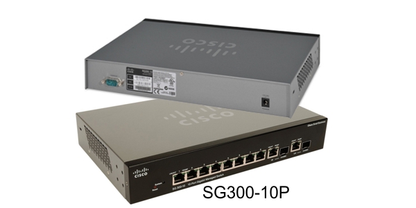
4) LinkSys SG300-10P Gigabit managed PoE Switch. About $280: ouch. A newer option for a gigabit managed PoE switch is the Linksys LGS308P: 8 ports gigabit PoE (instead of 10), but also supports the higher power 802.3at PoE and is available for about $140. The SG300-10P managed switch fully supports 802.1q VLANs. This switch is fanless: no need to listen to liftoff of the space shuttle here! Why spend so much money on the switch? You can spend less: see the following list of features we'll need.
Cisco Linksys SG300-10P 10 Port Managed Gigabit Switch with 802.3af PoE
Switch Features For a VLAN Segregated Network
A managed 802.1q VLAN capable switch. Each port is individually configurable to be in a tagged and/or untagged VLAN. This means the switch must be 'managed' or 'smart': an unmanaged switch does not have the ability to map VLANs to ports. When purchasing your switch, make sure it supports simultaneous tagged and untagged VLANs on the same port: this will simplify your setup and maintenance, IMHO.
Gigabit ports. I wanted to be able to transfer files between computers at maximum speeds so I opted for a switch with 10/100/1000 ports. Prices of gigabit managed switches are now so low that it is simply not worth considering buying a 10/100 managed switch.
PoE. I don't have 110VAC power near my Access Points. So the switch needs to provide the power to run my Access Points, Cameras, and VoIP telephones. There are two relevant PoE standards: the original lower power 802.3af (suitable for most PoE devices) and the newer higher power 802.3at (needed for some PTZ cameras and such). You could skip purchasing a PoE switch and save a lot of money: gigabit managed switches (no PoE) are available for around $50. So I'm basically forking over about an extra $90 (for a LinkSys LG308P) to purchase PoE because I don't always have 110VAC near my Access Points, Cameras, or VoIP telephones.
Fanless. A noisy switch is no fun if its in your office. PoE can require lots of power - meaning lots of heat - so if you need more ports (and therefore a switch with a fan), it might be better to put your switch in a remote location where you don't have to listen to the beast.
Update: after having PoE for a few years, it has been a very worthwhile addition since we now have 3 PoE Access Points to ensure excellent coverage inside and outside our Bed & Breakfast, two PoE VoIP telephones, and a PoE PTZ camera. The VoIP phones save us a LOT of money on our phone bills (less than $5/month total for our two desk phones using voip.ms), so the PoE has been incredibly convenient and cost effective.
What's Next - Creating Our VLANs
In the next part of our series, we'll discuss LANs and VLANs. We'll draw a simple network diagram to show how we'll use a VLAN to separate out our guest traffic. And we'll go over the reasons why a managed switch is so useful, and frequently necessary, when using VLANs.