This article is one of a multi-part series on setting up a segregated Guest Network, including a guest WiFi network, within a Home Network. It is essentially an introduction to Virtual Local Area Networks ( VLAN), provides a simple use case for VLANs and gives a complete set of recommended hardware plus details the setup of that hardware.
The series of Guest Network articles progresses as follows:
- We select a set of low cost hardware to meet our criteria of creating a Guest Network, including Guest WiFi, within our Home Network.
- We go into some detail why we use VLANs and a managed switch. Understanding VLANs is key to understanding how to build a guest network.
- We set up the TPLink TL-WA801N WiFi Access points. This is a very simple process where configure each AP onto our Home Network and configure the AP's WiFi to operate on our separate Guest Network VLAN.
- We set up our managed switch, a Cisco Linksys SG300-10P, to send Home Network traffic to only the Home Network devices and Guest Network traffic to only the Guest Network devices. And we show the special case of mapping the Guest Network Access Points onto both networks simultaneously.
- We begin preparing our main router, a TPLink TL-WR1043ND, to create and manage the VLAN traffic for our Home Network and our Guest Network. Since the WR1043ND does not come with 802.1q VLAN support out of the box, this article is where we install openwrt on the WR1043ND.
- Lastly, we configure openwrt on the TPLink TL-WR1043ND to create and manage all the VLAN traffic.
In this article of the series, Part 2, we discuss the principles and VLANs that we will be using to create our Guest Network. We'll use simple network diagrams to illustrate concepts, clarify our approach, and offer alternatives.
Review - What is a LAN
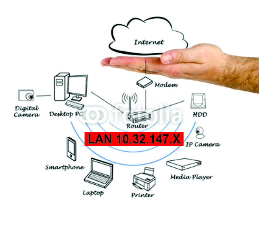
Before we jump into a discussion about VLANs, let's review what a LAN is: a number of Ethernet or WiFi devices all connected together that can talk to each other. They share a 'broadcast domain' to allow the devices to know about each other and cooperate. Here is a picture of a simple LAN: all the devices are in the same IP address range from 10.32.147.1 through 10.32.147.254.
Basics of a Single LAN
In the above example, we would define a LAN with the following characteristics:
- The router's IP address is 10.32.147.1. It is the 'gateway' that all our devices go to whenever they need to get out to the Internet.
- The mask for this LAN is 255.255.255.0: there can be up to 254 devices on this LAN.
- The router's DHCP server hands out IP addresses to each device as it connects to the network. For example, we may have set up DHCP to hand out an address in the range from 10.32.147.100 through 10.32.147.150 whenever a new device is plugged into the LAN (or connected via WiFi).
- The router passes the DNS addresses to the devices on the network. The Domain Name Service is the system that associates a URL name (www.alduras.com) with an IP address. All communications occur using IP addresses rather than names.
When a new device (PC, laptop, phone, etc.) connects to our LAN, it therefore gets the following information from the router:
- IP Address. The device's IP address, for example 10.32.147.100. The router's DHCP server generates this local IP address.
- Mask. The device's mask. In our example, this would always be 255.255.255.0, meaning this LAN can support up to 254 devices.
- Gateway. The gateway address to be used by the device. In our example, this is the router's address 10.32.147.1. The device will therefore go to the gateway any time it needs information about devices outside our LAN addresses (for example, for all Internet access).
- DHCP. The address of the DHCP server used to request the device's IP address. In a small network, this is virtually always the router's IP address, or 10.32.147.1 in our example.
- DNS. The address of DNS servers to query when trying to resolve a name to an IP address.
Approach #1 - Adding a Guest Network Using Two Physical LANs
In the above single LAN example, all our devices are in the same network: all the devices communicate with each other by virtue of being within the address range of 10.32.147.1 through 10.32.147.255. The highest address, 10.32.147.255 is the multicast address: the address that any device can use to broadcast a message to all devices within our LAN. Multicast never goes outside a LAN: it stays within the local network only.
This single LAN is fine if we trust every device equally and we don't have any need to throttle service to any particular device. This approach is quite sufficient for most home networks.
But what happens if we have guests in our home? Do we want them to have access to the files and computers on our LAN? Or do we want our guests to have their own private LAN to ensure security of our files and computers, but still give our guests access to the Internet?
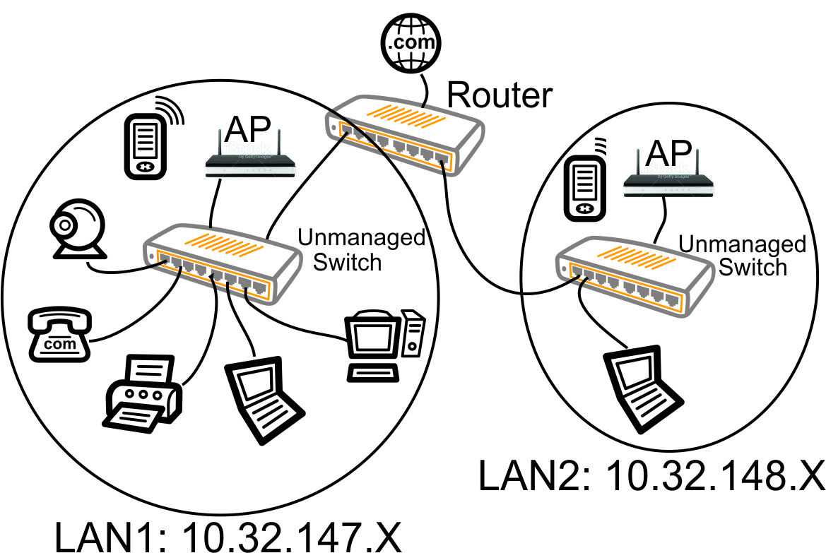
Before VLANs, the simplest method to create a second LAN would be to buy a second switch, buy a second WiFi access point, and run some wires to handle just LAN #2. We would add all the devices and wires to create a new LAN (the 10.32.148.X LAN) as shown in the following diagram. Note that each LAN has a unique IP range: this a requirement of separate LANs so the router knows which LAN is to be used (how to route the packets).
Approach #2 - Adding a Guest Network Using One Physical LAN With Two Virtual LANs - Unmanaged Switch
However, adding a second physical LAN is expensive and inefficient. Why buy the second unmanaged switch and run new wires (all that equipment on the right in the above diagram)? How about we just use all our existing wiring?
The concepts are still the same with our VLAN instead of our physical LAN. Each VLAN is its own world with its own unique set of IP addresses, otherwise the router does not know where to route packets.
In this approach (and all subsequent approaches), we still have only one Ethernet wire - one physical LAN - but now we essentially split that wire into two virtual wires, or Virtual LANs:
- VLAN1 - 10.32.147.x for our personal traffic
- VLAN2 - 10.32.148.x for our guest traffic
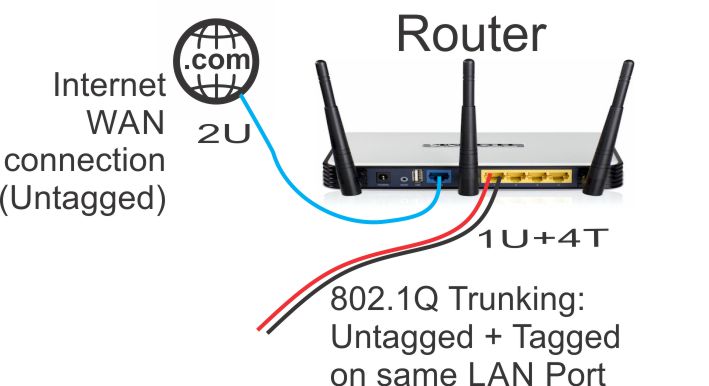
If we have a VLAN aware router, we simply ask it to put the VLAN1 traffic AND the VLAN2 traffic out on the same port of the router. There are two ways we can do this:
- We can output the VLAN1 traffic 'untagged' and the VLAN2 traffic 'tagged'. The advantage here is all the receiving devices of VLAN1 traffic do NOT have to be be VLAN aware: they will simply ignore the VLAN2 traffic.
- We can output BOTH the VLAN1 and LAN2 traffic as 'tagged' VLANs. Pandomonium ensues. Nothing talks because now every device has to be VLAN aware: every device has to be able to dissect the special VLAN traffic and pull it out of the packets. The packets are reaching the devices in this scenario, but the devices don't know what to do with the VLAN packets.

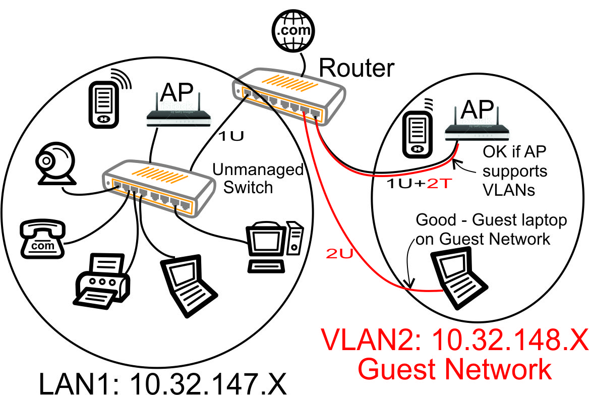
In the above diagram, each Ethernet cable is carrying both the VLAN1 traffic (the black VLAN1 untagged '1U' traffic) and the VLAN2 guest traffic (the red VLAN2 '2T' tagged traffic). When you see a red 'wire' alongside a black 'wire' above, it is NOT two different wires, but is instead a depiction of a VLAN connection with two (or more) sets of VLAN traffic traveling down the same Ethernet wire.
When we configure the router to send multiple VLAN traffic over an Ethernet connection and use an unmanaged switch, the VLAN1 and VLAN2 traffic is reaching every device, as shown above.
There are some problems with using the unmanaged switch in the above diagram:
- The Guest Laptop will automatically connect to the Main Home Network, not the Guest Network. The VLAN1 (Main Home Network) traffic is the untagged traffic so the Ethernet of the laptop will use that traffic by default. Many laptops do have a provision to connect to a tagged VLAN by editing the network device hardware settings, but requiring your guests to modify their laptop settings just so they are not using your main home network is impractical.
- The VLAN2 (Guest Network) traffic is needlessly being transmitted to all devices, not just the devices that need to access the Guest Network.
Tagged vs. Untagged VLANs
In our diagram above, we introduced the concept of tagged and untagged VLANs.
- An 'untagged' packet is just a standard Ethernet packet: every device on the network will look at the packet and determine whether they should receive the packet. In our diagrams here, notice we always have a 'U' (untagged) wire going to every device: that is the untagged VLAN that every device knows how to handle.
- A 'tagged' packet is essentially a hidden packet: every device on the network will ignore the tagged packet unless they are specifically looking for that exact VLAN tag number in the tagged packet. For a device to handle 'tagged' packets, that device must be explicitly configured to look for tagged packets . For example, if you want your PC to react to a tagged VLAN, you will need to set up the PC's Ethernet 'card' to look at only the traffic for a particular tagged VLAN number. In our diagrams here, notice we sometimes have a 'T' (tagged) virtual wire running alongside our physical 'U' (untagged) wire: we 'cheated' and created a second virtual Ethernet wire using our tagged VLAN.
In a nutshell: 'untagged' traffic just works without any special setup, but tagged traffic is that second (or more) Ethernet Virtual LAN that is ignored unless the receiving device is specifically looking for those tagged Ethernet frames.
You can only have one untagged VLAN on a port, however you can have many tagged VLANS on a port. If you try to put multiple untagged LANs on a port, it does not work.
Approach #3 - Adding a Guest Network using VLANs - Unmanaged Switch, Improved
With a bit of rewiring, we can utilize the unmanaged switch and the extra ports on the router to fix our problems with our prior approach. This change will work if we can physically move wires.
With a couple wiring changes (connecting the AP and guest laptop directly to ports on the 802.1q VLAN capable router), we have dramatically improved our network.
- All the devices on our main home network are receiving/transmitting only the VLAN1 10.32.147.X traffic. In VLAN parlance, we have placed VLAN1 untagged traffic (1U in above diagram) on the left port of the router.
- The guest laptop is receiving/transmitting only the Guest Network 10.32.148.X traffic. In VLAN parlance, we have placed VLAN2 untagged traffic (2U in above diagram) on the port of the router that is second from the right.
- The guest Access Point is managed from a home network IP address, but the WiFi is on the Guest Network. In VLAN parlance, we have placed both VLAN1 untagged traffic and VLAN2 tagged traffic (1U + 2T in above diagram) on the right port of the router.
We have accomplished our goal to separate the Home Network and Guest Network by using an 802.1q compliant router and performing a bit of knowledgeable rewiring.
Approach #4 - Adding a Guest Network using VLANs - Managed Switch
Although we accomplished our goal to separate out our Guest Network in the above scenario, we can make some notable improvements by replacing our unmanaged switch with an 802.1q compliant managed switch that has the ability to simultaneously map untagged and tagged traffic to any port (such as the Cisco Linksys SG300P).
Some of the advantages of upgrading to a managed switch:
- Complete flexibility of which VLAN traffic goes out on which port. We can map any VLAN tagged and/or untagged to any port. This ensures security and reduces unnecessary traffic: each device receives only the VLAN traffic appropriate for the device.
- We don't need to rewire anything like we did in the above scenario. The switch can receive all VLAN traffic from the router, then the managed switch can flexibly route traffic uniquely to each switch port as needed.
- We can place our Ethernet wiring in one physical location and not have to worry how our network may need to be rewired based on our changing needs. For example, when rewiring my house (or business), I simply ran every Ethernet wire to one closet and put a large managed switch in that closet.
- With the low cost of managed switches today, there is no compelling financial reason to buy an unmanaged switch. Managed gigabit switches are readily available for under $100.
So lets make a change and replace the Ethernet switch with a managed Ethernet switch. Now our VLAN based network can be cleaned up by configuring the managed switch to only pass traffic through the switch ports that make sense for our devices.
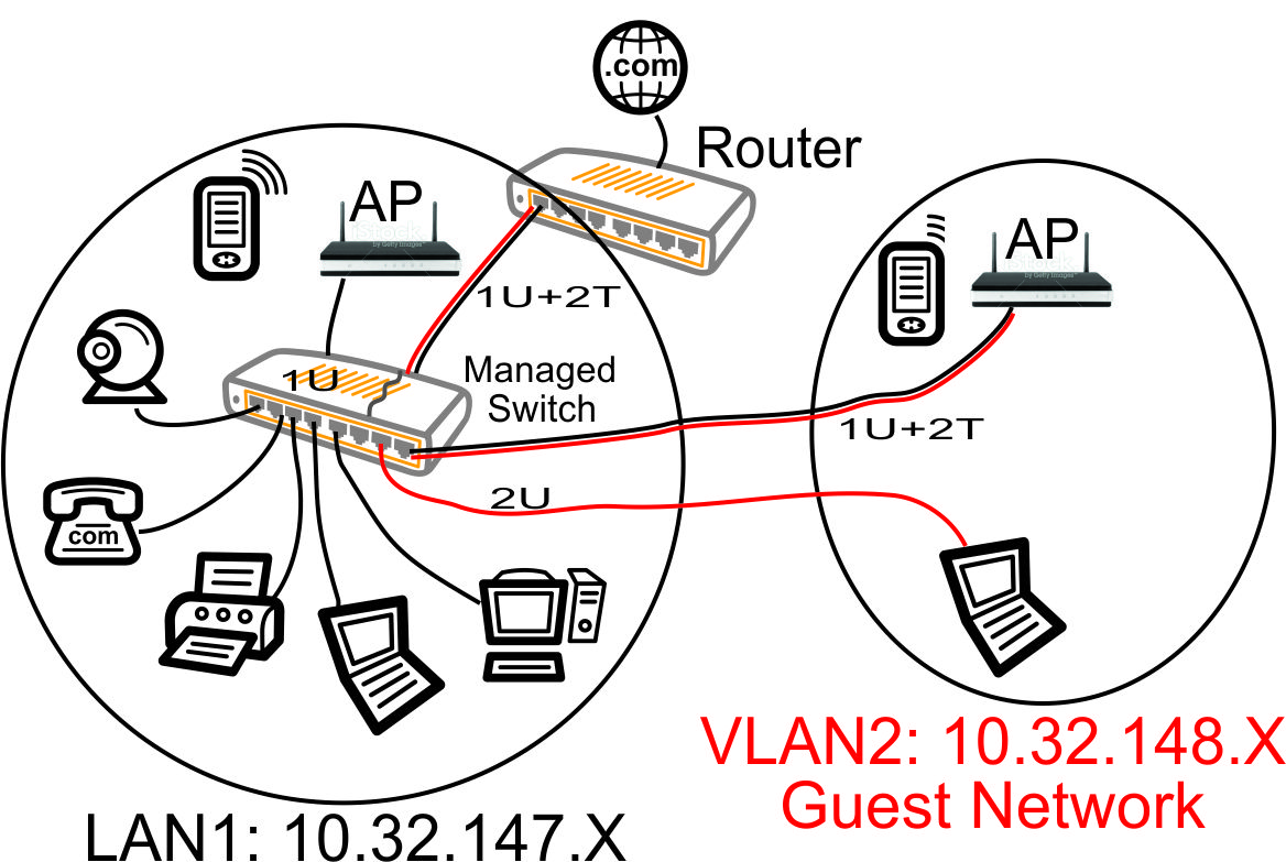
In the above diagram, red is VLAN2 traffic across our Ethernet wires, black is VLAN1 traffic, the 'U' means 'untagged' VLAN traffic and the 'T' means tagged VLAN traffic.
Our managed switch basically lets us 'carve up' the switch into a bunch of separate switches. We can overlap untagged and tagged traffic on each port of the switch in any manner we please.
Lets take a look at how we configured our managed switch above:
- Ports 1-6 (the left ports) are configured to pass the LAN1 traffic untagged to all the devices connected to the 10.32.147.x network. The VLAN2 traffic does not appear on any of those devices.
- Port 7 (second from right) is configured to take the tagged VLAN2 traffic from the router, strip off the tags, and send VLAN2 traffic untagged out port 7. So this makes it real easy to configure the laptop connected to port 7: it is just a normal Ethernet configuration that does not have to be VLAN aware. The laptop is on our guest 10.32.148.x network and cannot access any files or computers on the 10.32.147.x network (assuming the router's firewall is configured to prevent bridging). So now we can safely host a guest laptop without worrying about that laptop affecting our personal home machines. And the guest just plugs in to the Ethernet, lets DHCP hand out an address in a normal fashion, and enjoys high speed Internet access.
- Port 8 (rightmost) is configured to pass the VLAN1 traffic untagged and the VLAN2 traffic tagged to the guest access point. That lets us put the configuration web page of the AP at one of our 10.32.147.x VLAN1 addresses, but puts the WiFi on our 10.32.148.x VLAN2 guest network. So we can manage the AP from our home computers, but the guests only get into the guest WiFi network. This requires an AP that supports SSID to VLAN mapping, such as the TPLINK TL-WA801ND Access Point.
- The uplink port of the managed switch (shown at the rear of the switch in the diagram above) receives VLAN1 traffic untagged and VLAN2 traffic tagged. All traffic is passing over this trunk port between the switch and the router.
802.1Q - Router Required Feature for VLANs
When purchasing a router, you'll need one that supports 802.1Q VLANs in order to set up your segregated guest network. This is a function of the model of switch chip on your router: not all switch chips support the simultaneous tagged and untagged VLANs as we have shown in the above drawings (when there are red and black side-by-side virtual wires in the above diagrams).
If you decide to install a managed switch (approach #4 above), it will also need to support 802.1Q VLANs. I highly recommend a managed switch since it makes it so easy to 'carve up' your network into exactly what you may need, regardless of location or wiring. If all you're doing is setting up some WiFi access points on their own guest network (not setting up any wired Ethernet separate networks), then the managed switch is of less importance.
When you look at the switch chip features of your router and managed switch, you will see the following terminology related to VLAN port configuration:
- Access Ports. These are ports that input and output ONLY untagged VLANs. They will NOT work for our guest network since they essentially do not support VLANs.
- Trunk Ports. These are ports that can output one untagged VLAN (the 'native' VLAN which us usually VLAN1) and any number of tagged VLANs. For our guest network using VLANs, it is sufficient to use Trunk Ports.
- General Ports (Hybrid Ports). These are ports that can map any tagged or untagged port to any other tagged or untagged port. In complex configurations, this flexible mapping can be used to speed up VLAN to VLAN switching by doing the switching at 'wire speeds', however there is no need for this capability in any of our guest network setups. Our guest network setups are careful to configure firewall rules between networks, so the router CPU must get involved, and therefore these 'wire speed' capabilities are of little use in our routers.
Some brands/versions of router Software will refer to Trunk Ports and mean ports that can output ONLY tagged VLANs: they don't support the one untagged native VLAN simultaneously on that Trunk port. Openwrt Version 18 seems to do a very good job of supporting simultaneous tagged/untagged VLANs on an 802.11Q Trunk port on many router models (if the switch chip supports it), but you will want to verify that capability before beating your head against the wall trying to get VLANs to work on your router.
If you refer to any of the Learning Articles here on this website (alduras.com) for routers I have set up with openwrt, they each support 802.1Q trunking.
When purchasing your router, it seems to be much too difficult to determine if they are truly 802.1Q capable. It seems to take a lot of careful and time-consuming searching. Do be diligent to search for that 802.1Q feature when you purchase your guest network router.
What's Next - Configuring the AP, Router & Switch
So now we have a nice, secure guest network together with a separate private home network. We'll configure the rules in the router firewall to keep VLAN1 and VLAN2 separate (however, maybe we'll allow VLAN1 to access VLAN2, but not vice versa).
Now that we understand the basic concepts of how we want to use VLANs and the managed switch to create our separate networks, let's go on to the next part in our series where we configure our Access Points.
Next article: Configuring the Access Points.
Articles in This Series:
- Guest Wifi Network - Part 1 - Device Selection
- Guest Wifi Network - Part 2 - Why VLANs
- Guest Wifi Network - Part 3 - Setting Up the TPLink TL-WA801N Access Points
- Guest Wifi Network - Part 4 - Setting Up the Cisco Linksys Sg300-10P Managed Switch
- Guest Wifi Network - Part 5 - Installing Openwrt on the TPLink TL-WR1043ND Router
- Guest Wifi Network - Part 6 - Setting Up the TPLink TL-WR1043ND Router
Excellent article!!!
You use DHCP addresses 10.32.147.100 thru 150
And 10.32.148.100 thru 150
My router comes with a default address of 192.168.0.1
Can I use DHCP addresses 192.168.0.100 thru 150
And 192.168.1.100 thru 150 ?
Yes, those will work, however I tend to avoid 192.168.0.X and 192.168.1.X since they are used by tons of other devices, so I pick addresses ranges I think will be unique to avoid any conflicts in the future. That is, because I find myself connecting new devices into my network fairly often, those new devices typically start out at a specific IP address - and those are frequently somewhere in the 192.168.0.X or 192.168.1.X range.
It can be a real nuisance if those new devices coincidentally have an IP address that is already being used by some device on my existing network: weird, difficult-to-understand things happen when two devices have the same IP address. So that's why I pick IP addresses in the 10.X.X.X range: you rarely see devices that come from the manufacturer with a default IP address in that range.
Here's the IPV4 address ranges you are allowed to pick for your LAN (where X is any number from 0 - 254, avoid 255 since it is special in some cases):
That above list gives you thousands of choices when setting up your network.
Here's the IPV4 address ranges I would avoid from that above list because they tend to be the defaults for many devices (we don't want to plug in a new device and have it's default IP address conflict with an existing device on our network):