
This article is one of a multi-part series on setting up a segregated Guest Network, including a guest WiFi network, within a Home Network. It is essentially an introduction to Virtual Local Area Networks ( VLAN), provides a simple use case for VLANs and gives a complete set of recommended hardware plus details the setup of that hardware.
The series of Guest Network articles progresses as follows:
- We select a set of low cost hardware to meet our criteria of creating a Guest Network, including Guest WiFi, within our Home Network.
- We go into some detail why we use VLANs and a managed switch. Understanding VLANs is key to understanding how to build a guest network.
- We set up the TPLink TL-WA801N WiFi Access points. This is a very simple process where configure each AP onto our Home Network and configure the AP's WiFi to operate on our separate Guest Network VLAN.
- We set up our managed switch, a Cisco Linksys SG300-10P, to send Home Network traffic to only the Home Network devices and Guest Network traffic to only the Guest Network devices. And we show the special case of mapping the Guest Network Access Points onto both networks simultaneously.
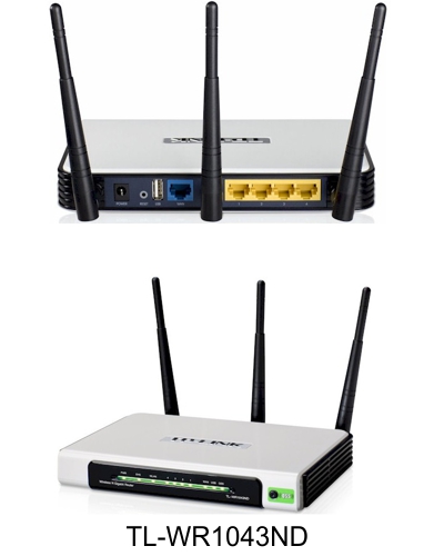
- We begin preparing our main router, a TPLink TL-WR1043ND, to create and manage the VLAN traffic for our Home Network and our Guest Network. Since the WR1043ND does not come with 802.1q VLAN support out of the box, this article is where we install openwrt on the WR1043ND.
- Lastly, we configure openwrt on the TPLink TL-WR1043ND to create and manage all the VLAN traffic.
In this final article of the series, Part 6, we configure openwrt of the TPLink TL-WR1043ND with the VLANs we need to create and maintain our separate Guest Network and Home Network.
VLANs to Be Used
- VLAN1. The home network at 10.32.147.X. These devices are all our personal devices include laptops, desktops, phones, printers, etc.
- VLAN2. On the TPLink WR-1043ND router, VLAN2 is the WAN port. This is connected to a cable modem in our case.
- VLAN4. This is the guest network at 10.32.148.X.
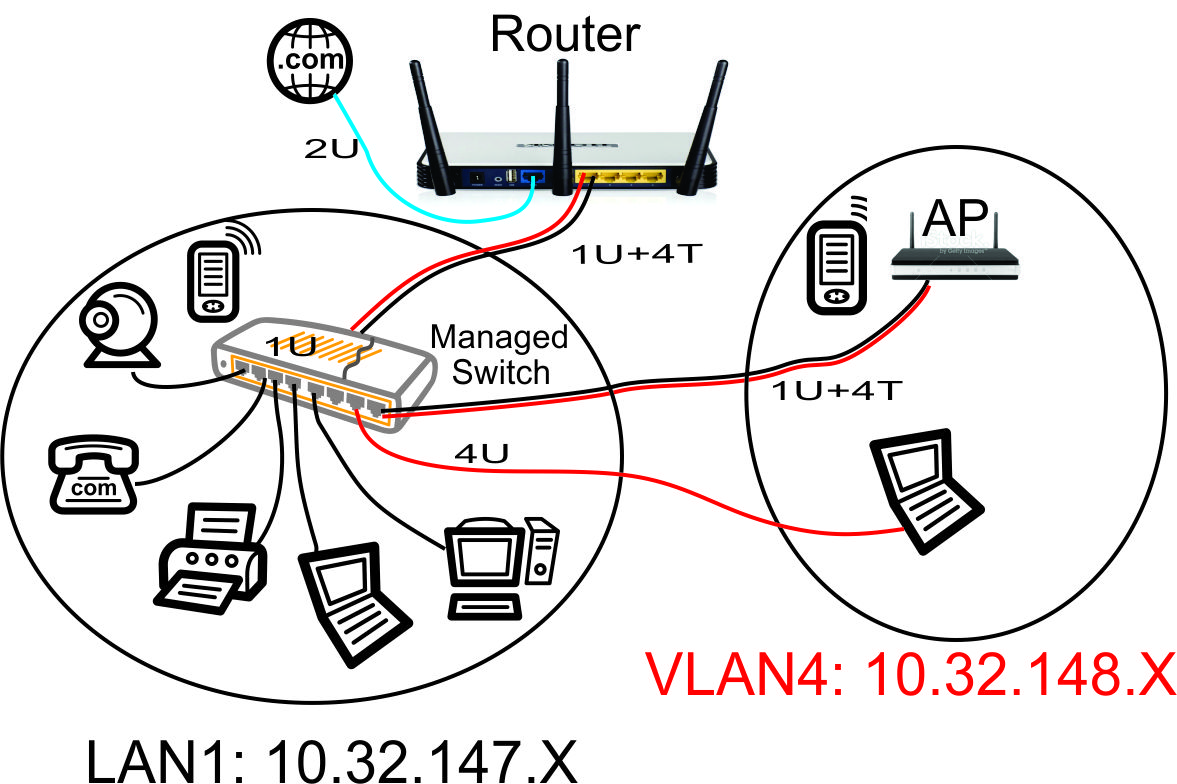
The above network diagram shows how we defined the ports on our Cisco Linksys SG-300-10P Power Over Ethernet (PoE) managed switch in a previous article.
Our guest WiFi Access Point, configured in a previous article in this series, is shown in the upper right hand corner. This Access Point will hand out WiFi IP addresses in the guest network range of 10.32.148.X. To make it easy to configure the Access Point from our home network, we put the AP's web configuration page on our home network with the 10.32.147.X range. This will prevent guests from being able to modify the AP settings.
If you have the version 2.X hardware, it uses an Atheros AR8327N switch chip instead of the Realtek RTL8366rb that is used in the V1.X hardware. It appears from the documentation of openwrt ticket #12181 that the 'Barrier Breaker' V14.07 Stable image for V2.X hardware does NOT have the 802.1q VLAN support. If your VLANs do not work with V2.X hardware, please check the status of openwrt ticket #12181 and use the appropriate version of openwrt. So buying V1.X hardware might be easier 🙂
Login to Openwrt
Once the firmware upgrade is complete, you will see the front panel lamps on the WR1043ND light up with the SYS lamp on steady. Re-enter the IP address 192.168.1.1 in your browser.
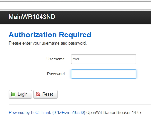
The default user name is 'root' and there is no password at first login. Complete the login and create a new password, as prompted.
Setup WAN Interface in Openwrt
Go to Network->Interfaces. Click on WAN. Following is a shot of my WAN setup. It required no changes since my WR1043ND plugs into a cable modem that has its own DHCP server. So the WR1043ND is simply a DHCP client on its WAN port.
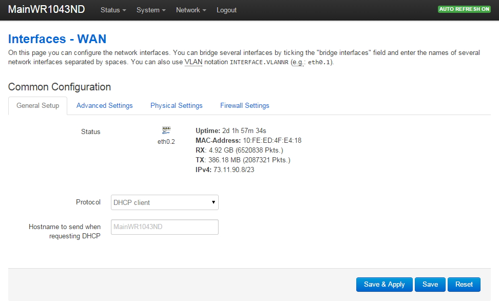
Please note there is considerable documentation on the openwrt WR1043ND web page about the 'WAN Port Disable' bug. I DID NOT experience this problem, however I thought I did! My Comcast Docsis 3 cable modem is very picky about replacing the router connected to the cable modem: it will not allow a new device to be plugged in without repowering the cable modem. So once I connected the WR1043ND to the cable modem and cycled the power on the cable modem, the WR1043ND WAN port picked up an IP address from the cable modem and began working fine.
Verify your WAN port is connected before continuing: you should see the uptime increment in the above screen.
Setup LAN Interface in Openwrt
Go to Network->Interfaces. Click on LAN. Following is a shot of my LAN setup.
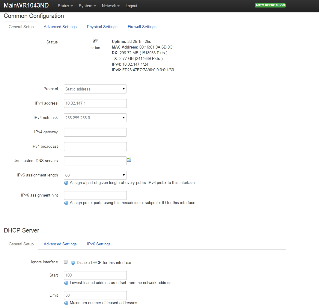
Referring to the network diagram at the beginning of this article, we set up the LAN to have the router at 10.32.147.1, the mask to 255.255.255.0 (maximum 254 addresses on LAN), and the DHCP to provide addresses from 10.32.147.100 through 10.32.147.149 for our main home network devices.
Setup VLAN4 Interface in Openwrt
Go to Network->Interfaces. Click on 'Add New Interface' and create a new VLAN named VLAN4 on eth0.4.
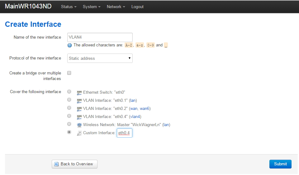
Your screen will not have the already existing VLAN Interface "etho.4" as shown above (the fourth radio button down in the 'Cover the following interface' list). You will click on 'Custom Interface' and enter 'eth0.4' to create the interface (as shown).
Note that we are NOT creating a bridge here (do not check the 'Create a bridge over multiple interfaces' checkbox): we want the VLAN4 guest network to be completely standalone.
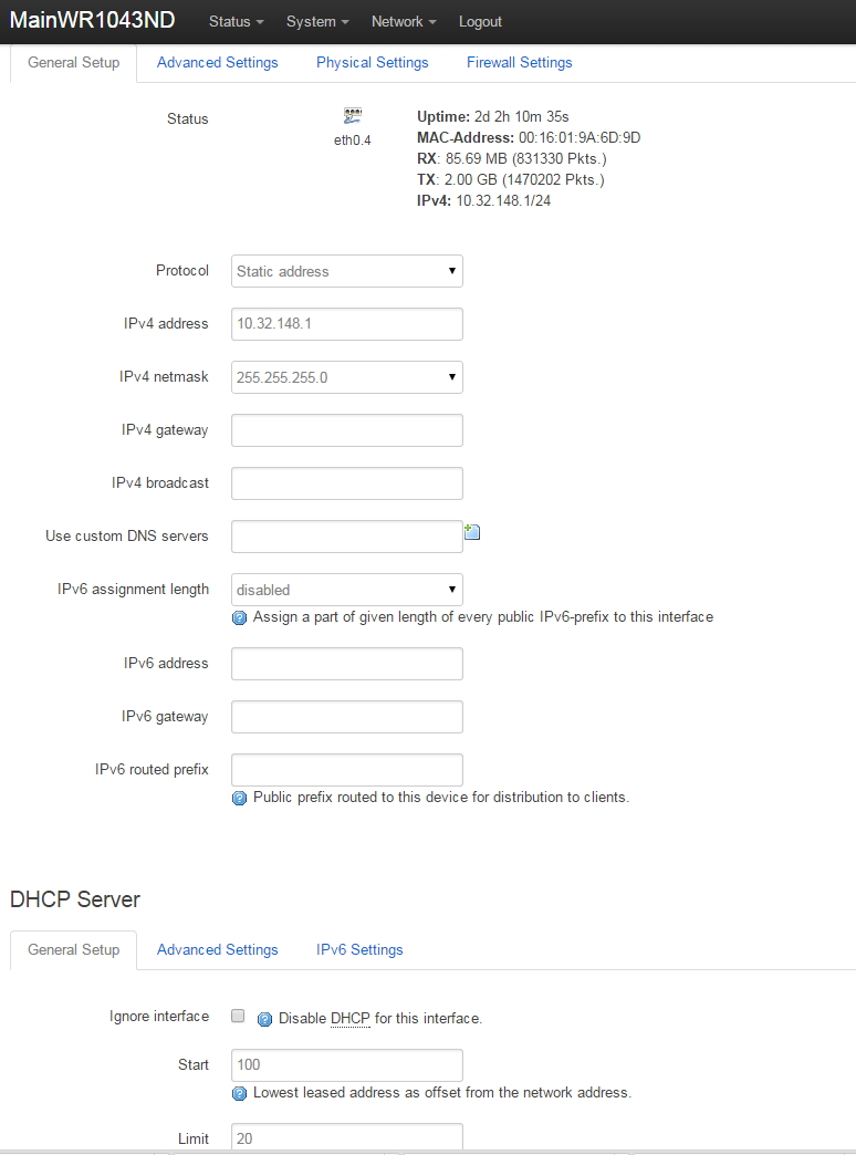
Setup of VLAN4 is very similar to the interface 'LAN'. Differences are:
- Router address of VLAN4 is at 10.32.148.1. The LAN that we created earlier is at 10.32.147.1.
- On VLAN4, I decided to hand out a maximum of 20 DHCP addresses on the guest network. The main home network on the LAN interface will generate up to 50 IP addresses with DHCP.
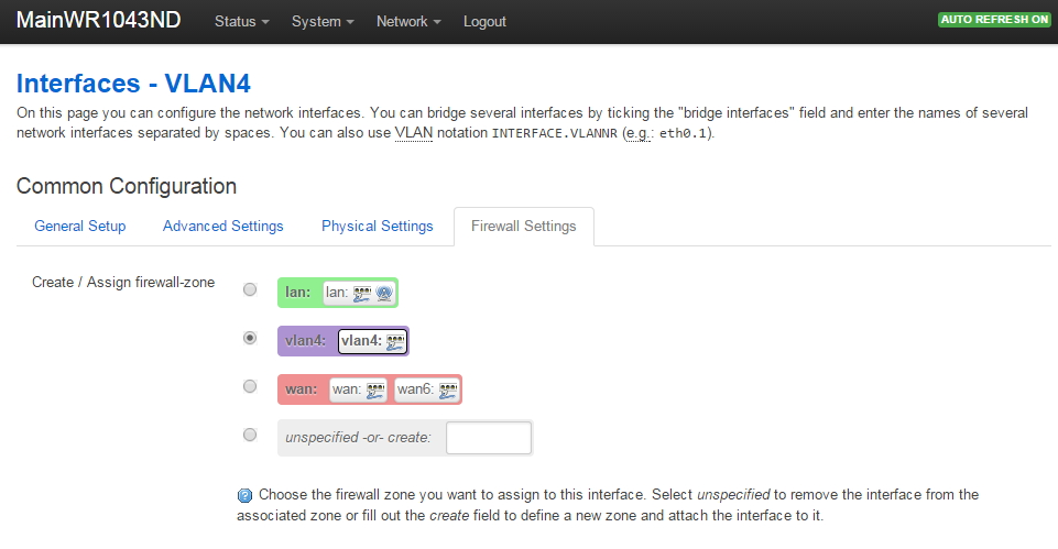
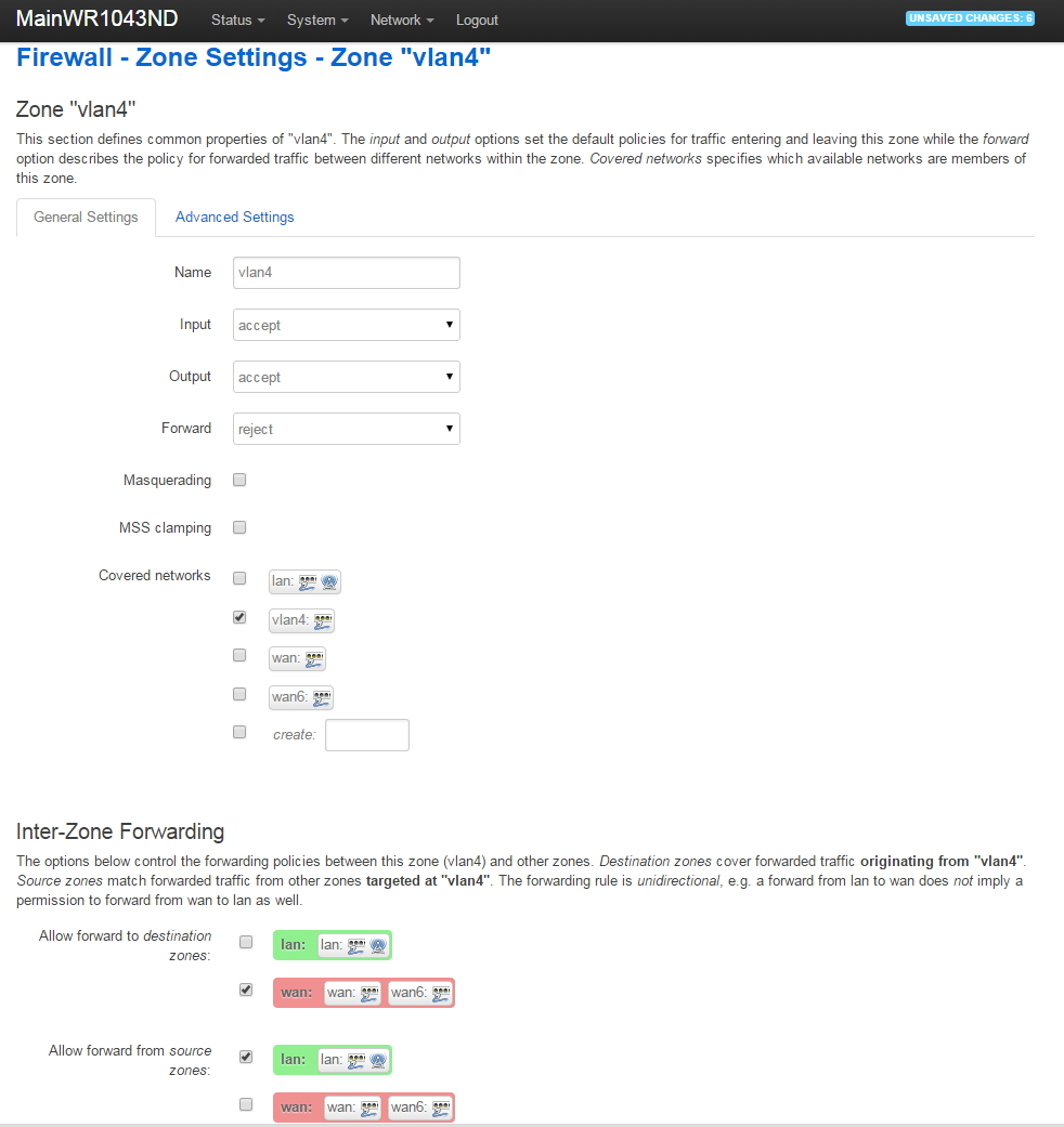
- Under the Firewall Settings tab for VLAN4, we put VLAN4 in its own firewall zone that we create and name VLAN4. Under Firewall Settings, click on 'unspecified-or-create', enter 'vlan4', then press 'Save and Apply'. After doing that, your VLAN4 Firewall Settings will look like this:
Your Network->Interfaces should now look like this:
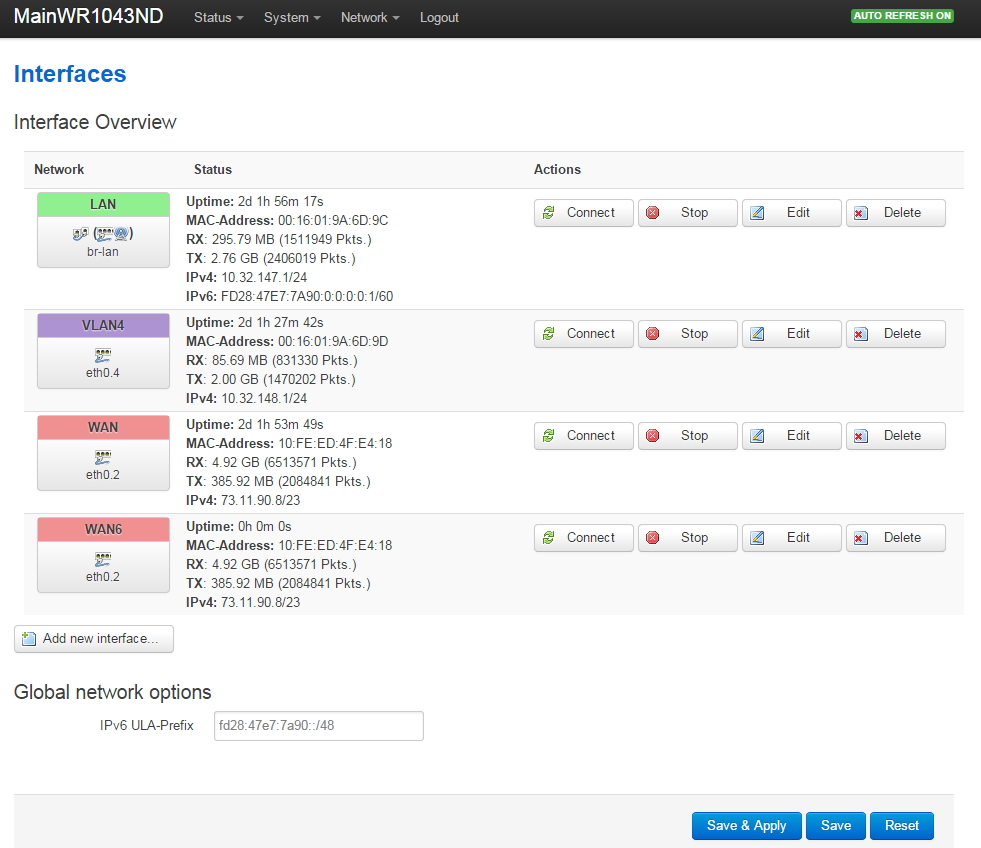
Note I did manually set MAC addresses for the LAN and VLAN4 interfaces, otherwise the system uses the same MAC address for every interface. Seemed weird to me...
Start Sending VLAN4 Traffic to Managed Switch
Go to Network->Switch. Click on 'Add' and send the VLAN4 traffic out the router port that is connected to the Cisco Linksys Managed Switch. In my case, Port 1 of the router is connected to the Cisco Linksys managed switch. Be careful here: the port drawing seems backwards to me so I just disconnected the Ethernet cable to watch where traffic disappeared and used that as the correct port on the router.
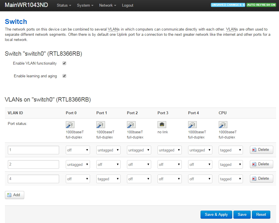
Port 0 is the WAN port, Ports 1 through 4 are the LAN ports (the openwrt drawing doesn't match the router unless you look at it from the rear), and Port 5 is the CPU.
After pressing add, enter the VLAN ID '4', set Port 1 to transmit/receive 'tagged' traffic and be sure to also set the CPU to transmit/receive tagged traffic.
We now have tagged VLAN4 traffic going to the managed switch, but we can't ping anything yet because we need to set up the firewall rules for VLAN4.
Configure VLAN4 Firewall Settings
Go to Network->Firewall. You'll see that the firewall rule named vlan4 is currently set to 'Reject' and there is no traffic allowed from the LAN to VLAN4. We will modify the firewall settings so they end up looking like this:
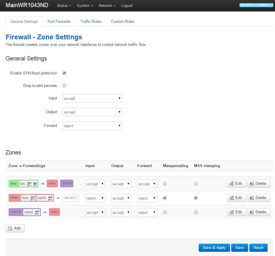
Under the Zones, click on the vlan4 edit button and make the following changes to allow vlan4 traffic out to the WAN (give vlan4 access to the Internet):
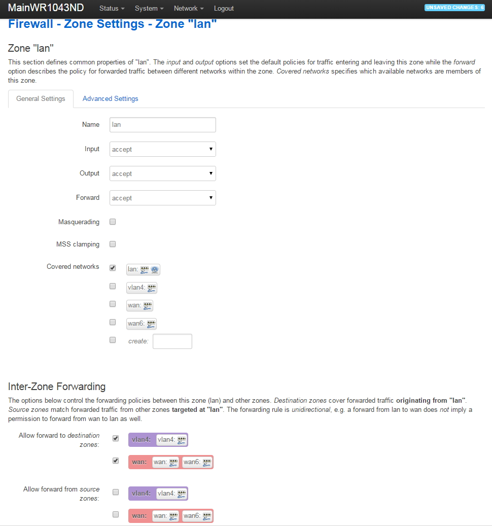
After saving the vlan4 zone firewall settings, go back to Network->Firewall, go down to the lan zone, then click on the lan Edit button. Make the following changes to allow the lan to access devices on vlan4 (but not vice versa):
Run in Circles, Scream and Shout
Would you believe we're done? Hooray!
You should now have a Guest Network that can connect to the Internet but is fully isolated from your main Home Network.
Articles in This Series:
- Guest Wifi Network - Part 1 - Device Selection
- Guest Wifi Network - Part 2 - Why VLANs
- Guest Wifi Network - Part 3 - Setting Up the TPLink TL-WA801N Access Points
- Guest Wifi Network - Part 4 - Setting Up the Cisco Linksys Sg300-10P Managed Switch
- Guest Wifi Network - Part 5 - Installing Openwrt on the TPLink TL-WR1043ND Router
- Guest Wifi Network - Part 6 - Setting Up the TPLink TL-WR1043ND Router
Thanks for the detailed and great tutorial!
Now I have my guest WLAN running fine even with different hardware.
Works fine. Thanks a lot!