Overview
This post covers installation of v18 openwrt on a Mikrotik RouterBoard 493G or 450G. Version 18 openwrt is the latest version as of November 2018. The specific RouterBoard example here is an RB493G, but this procedure will work for most RouterBoards supported by openwrt. For example, the procedure to install onto a Mikrotik RB450G is identical to the procedure covered here. Other openwrt supported RouterBoards models require, at most, only one small change to this procedure (selecting the correct names of the initramfs and sysupgrade .bin files).
Version 18 openwrt made a significant simplifying change to the RouterBoard installation procedure: openwrt now installs and upgrades directly from the LuCI web interface of openwrt. This means the procedure to install openwrt on a Mikrotik RouterBoard is now just two steps:
- Step 1. Temporarily install openwrt into the RAM of the RouterBoard by using the RouterBoard's ability to boot from an Ethernet network (netboot).
- Step 2. Use the temporarily-installed Ram-based openwrt to run the openwrt LuCI web page that installs/upgrades openwrt directly into the flash memory of the Routerboard.
Step 1 and 2 are essentially identical for all RouterBoard models, with the primary difference being the selection of the specific initramfs (Step 1) and sysupgrade .bin (Step 2) file names to download from the openwrt website. See the
Mikrotik Table of Hardware - Firmware Downloads
for the specific file names to be used for any of the openwrt supported Mikrotik RouterBoards. The RB493G and RB450G use the exact same file names.
Another simplifying change to the installation procedure of openwrt is my recommended use of the Windows freeware software package 'Tiny PXE'. Used during Step 1, Tiny PXE allows the use of the default Mikrotik BOOTP netboot protocol without any changes to the RouterBoot setup. This means that a serial connection to the RouterBoard is no longer absolutely necessary since a RouterBoard can be forced to netboot by simply pressing and holding its Reset button when powering up.
Tiny PXE is such a simplifying solution to the netboot of Mikrotik RouterBoards that I have since modified the openwrt wiki to reflect the suggested use of Tiny PXE. In the former openwrt wiki documentation, you would set up some kind of a temporary DHCP/BOOTP/TFTP server by picking from a list of alternatives that were text and Linux oriented. Tiny PXE removes the complexity of DHCP/BOOTP/TFTP setup with its very simple Windows 'portable' standalone application that is well suited to the RouterBoards since Tiny PXE so easily supports the default BOOTP boot protocol of RouterBoot. Much credit needs to be forwarded to its author for providing such a handy and well-implemented netboot tool.
Background
Is the Mikrotik RB493G the Ultimate openwrt Router?
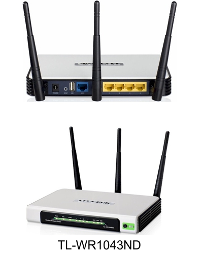
We recently upgraded our cable modem to a DocSis 3.1 compatible unit, the Motorola MB8600. DocSis 3.1 offers substantially lower latency internet access: web pages begin to download noticeably faster with this new cable modem. Our download speeds with this new cable modem are now measuring in excess of 100 MBits - which appears to be very near the limit of our existing TpLink TL-WR1043ND router's WAN capabilities. As Comcast continues to improve our download speeds, we want to be sure we have a router that can keep up.
We have also upgraded all our PCs here to Windows 10 laptops with USB3.0 ports that support up to 5 GB/S speeds. Our PCs now use USB3.0 to gigabit Ethernet adapters to connect to our wired Ethernet, or a Thunderbolt 3 docking station to 'permanently' connect to wired gigabit Ethernet.
We've been running openwrt on our TpLink router for the last few years and have had zero crashes of the router: openwrt is phenomenally reliable. I have experience with a number of router brands through my industrial networking installations business: Cisco, Linksys, Netgear, ZyXel, Mikrotik, TPLink, Ubiquiti, etc. and have found I prefer the simplicity, reliability and cutting edge features of openwrt over all the various brands I have used.
So our small office is now characterized by:
- Gigabit PCs
- Gigabit switch
- A low latency, high bandwidth Internet cable modem that is in excess of 100 MBit Ethernet capabilities.
- A router with five 10/100/100 Ethernet ports that seems to be having trouble utilizing our DocSis 3.1 router's speed, and just does not have enough gigabit ports for my needs: I am tired of plugging and unplugging computers while I am working on them.
It's time to upgrade our router. The features we would like:
- openwrt compatible (on the openwrt hardware compatibility list)
- Eight or nine 10/100/1000 Ethernet ports
- 2.4/5GHz WiFi. 802.11 a/b/g/n
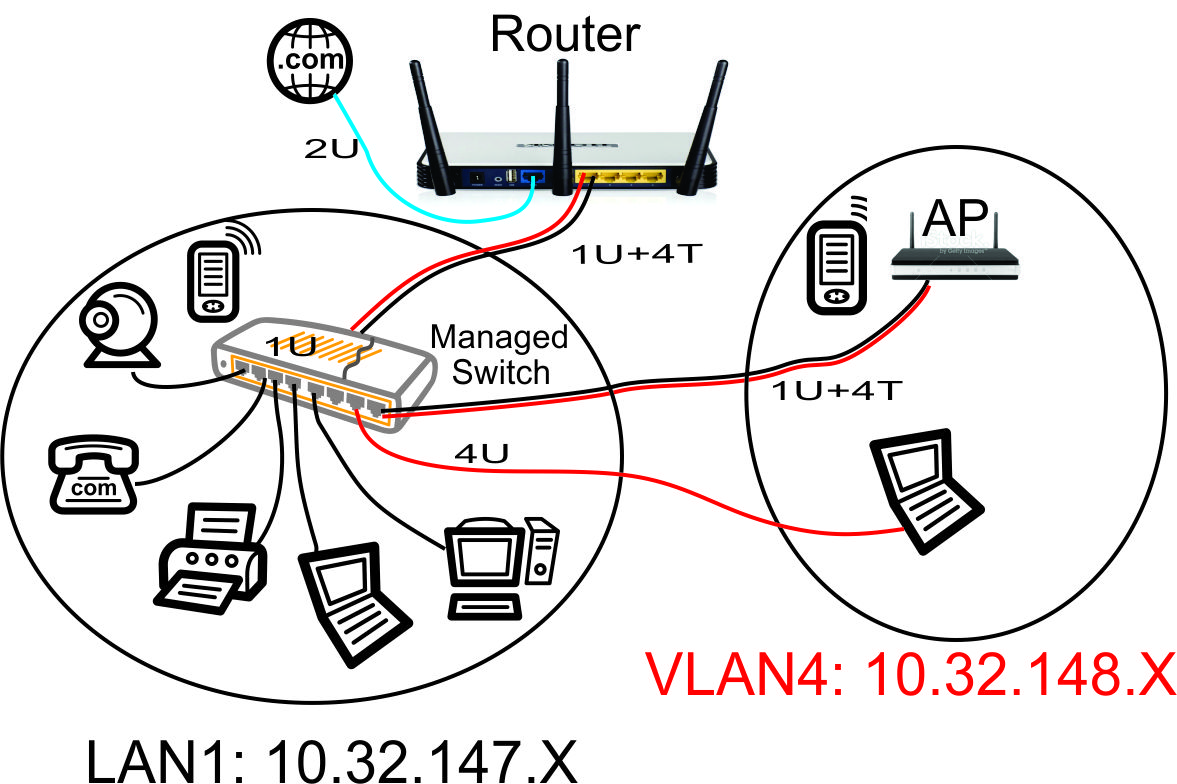
- 802.1Q Trunking VLAN support for segregated (guest) LAN & WiFi networks
- FQ_CoDel Smart Queue Management (SQM) to take advantage of the DocSis 3.1 extremely low latency capabilities
- Desktop size (not rack mount)
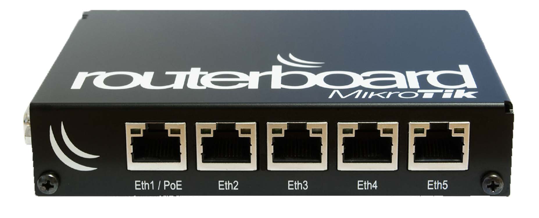
This list above yields one candidate: the Mikrotik RB493G. I have been using the Mikrotik hardware (and RouterOS software) for years in my industrial installations and found their hardware to be extremely robust. That only makes sense since many of the Mikrotik routers are installed in outdoors applications: these are indeed high quality routers.
The Mikrotik RB493G is a highly capable small router with a 680 MHz MIPS processor, 256MB RAM and 128MB NAND flash. It has a serial port, SD card slot, will run from a 8-28V DC supply and is rated for -40 to +70 degrees C. They are designed to be used in some pretty challenging outdoor environments so they are robust. They ship with a proprietary Mikrotik OS that has a surprisingly full feature set for router applications. These routers give Cisco a run for their money at a fraction of the cost. The irony of the full feature set is that this router is difficult to learn: we simply don't need most of the features and their immense routing flexibility is not used for home, small office or industrial applications.
We could just install a stock RB493G with the optional 2.4/5GHz R52HnD WiFi, leaving the stock RouterOS on the RB493G. However, in spite of using the Mikrotik routers for years, I've never been able to warm up to the extremely complex RouterOS. I generally spend way too long trying to implement any new feature on RouterOS so I would prefer that our office router runs on openwrt. Openwrt is remarkably simple to configure and modify for just about any scenario you can dream up.
VLAN Support on the RB493G and RB450G
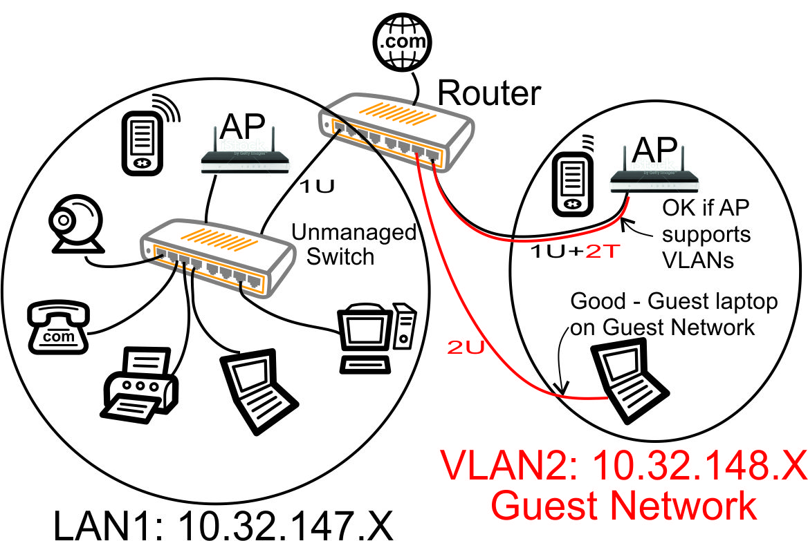
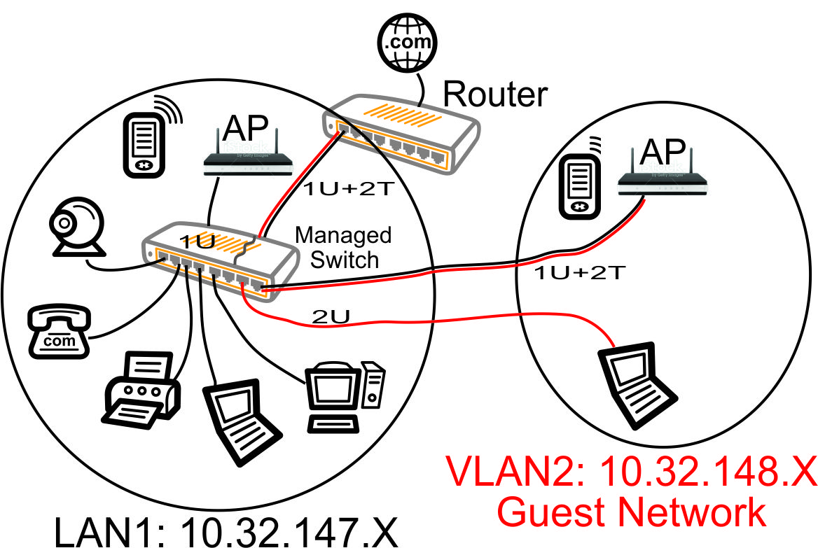
Many of the articles here on this website discuss setting up a segregated guest WiFi network. Because our applications all use VLANs, it is imperative that we select a router with 802.1Q Trunking VLAN support.
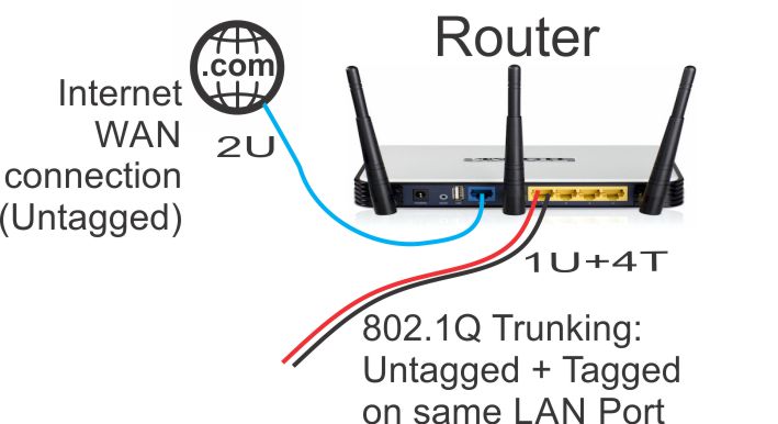
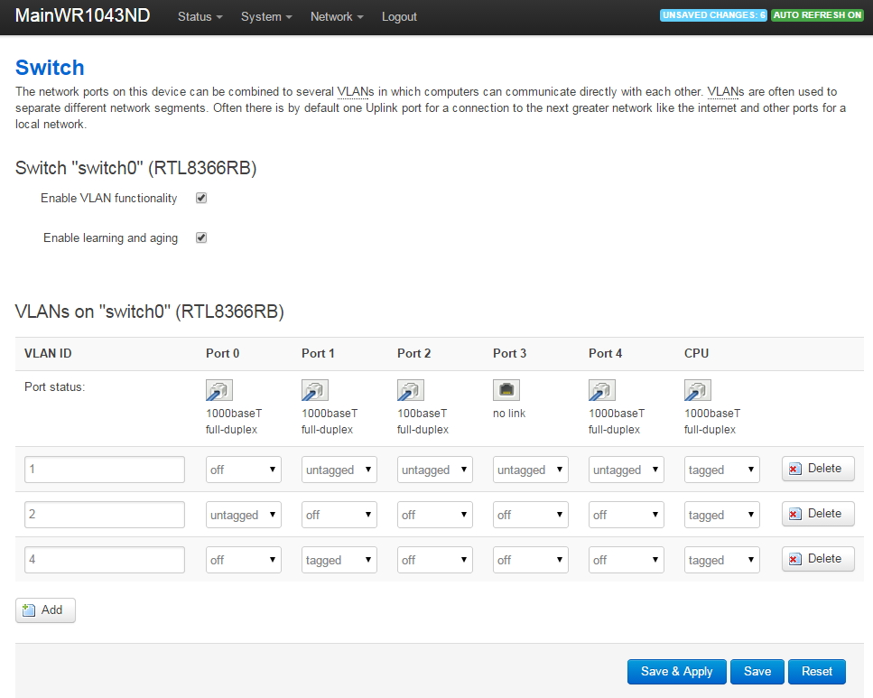
The Atheros AR8316 switch chips on the RB493G (one AR8316 on the RB450G, two AR8316's on the RB493G) do support 802.1Q Trunking with version 18 of openwrt. 802.1Q Trunking allows us to map one untagged VLAN and multiple tagged VLANs onto a port: a required feature when creating a guest LAN or WiFi network.
However, the AR8316 chips do NOT support VLAN 'hybrid' switching (sometimes called 'general' switching in some managed switches), but that is a feature of little import in our router configurations. If our router was serving numerous VLANs where we needed routing between VLANs at wire speeds, then 'hybrid' switching would be handy to speed up communication across VLANs. However, since we run each of our VLANs through the router CPU for firewalling purposes anyhow, there is nothing to be gained by 'hybrid' switching for any of our applications here in our small office.
V18 openwrt Installation Procedure on the Mikrotik RB493G
You can find the openwrt build instructions wiki for the Mikrotik Routerboard 493G here:
https://openwrt.org/toh/mikrotik/rb493g
And the openwrt Common Procedures for Mikrotik Routerboard Products wiki here:
https://openwrt.org/toh/mikrotik/common
I wrote much of the the above openwrt version 18 Mikrotik documentation (see the above links). So you will see many similarities in this document and the openwrt wiki. However, the openwrt wiki information pages are mostly text, whereas these instructions here contains LOTS of screen shots. My instructions here are Windows 10 oriented and reflect the much simpler, newer 'sysupgrade' style images of version 18 openwrt. I've been using Unix and Linux for 25+ years but my daily machine is my Windows 10 laptop. Virtually every form of Industrial software runs from Windows so that's my first line of defense for my paying jobs. My apologies to the Linux fans: I love Linux, but I'm really familiar with Windows 10 by virtue of professional necessity.
My main computer is a Windows 10 64 bit laptop with its maximum 16GB RAM and a 2 TB flash drive. You will NOT need a very high end PC to accomplish this openwrt installation: pretty much any Windows 10 (or Windows 7) laptop/PC should be able to perform this installation.
Step 1 - Gather/Purchase All the Hardware You Will Need
In our example, we will be using the following equipment:
- Mikrotik RB493G circuit board
- Mikrotik R52HnD miniPCI 2.4/5GHz WiFi card
- Quantity 2 Mikrotik ACSWIM 2.4/5GHz antennas with MMCX connectors
- Mikrotik CA493 case
- Mikrotik compatible 'wall wart' power supply such as the Maxxwave 24V 24W
- An Ethernet cable to connect from your existing router to the RB493G. We will use this same cable to also connect from the RB493G to your laptop/PC. It needs to be long enough to conveniently connect to your existing router (or switch) and the RB493G: I use a 7 foot Ethernet cable.
If you don't want to assemble the above RB493G parts yourself, you can purchase a fully assembled RB493G with the above WiFi card directly from Baltic Networks.
Optional Hardware Only needed to connect to the serial port to view console or change boot settings of the RB493G. This is handy to debug the success of your netboot, but is not absolutely required when you use the TinyPXE software described in this document.
- A USB to serial RS232 adapter. We will use this to connect our PC to the serial port on the RB493G. There are many choices of USB to RS232 adapters available, however I can highly recommend the Tripp Lite Keyspan USA-19HS. I use it in my industrial PLC business: this has a Windows software driver proven to be compatible with a large number of software packages that require RS232 serial support. This device is only used while we are installing openwrt.
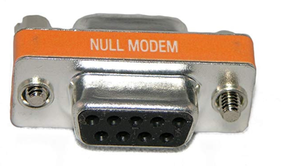
- A null modem RS232 serial DB-9 female to DB-9 female adapter.
This device is only used while we are installing openwrt.

Step 2 - Download the Needed Files
In my case, I had purchased my RB493G quite some time ago, so it was running a very old version (V5.2) of RouterOS. Because we are careful to save the existing RouterOS license before starting any of the installation of openwrt, we need to run the Mikrotik Windows App 'WinBox' to save the existing License File (this cannot be done using the Mikrotik 'WebFig' web-based interface).
However, if you have an old version of RouterOS, the WinBox Windows application is not compatible with Windows 10. So, ironically, we need to start off by updating the RouterOS to the latest version in order to get an updated WinBox that will work with Windows 10. Note: you cannot just download WinBox from the Mikrotik webpage because old versions of RouterOS will not necessarily work with newer versions of WinBox.
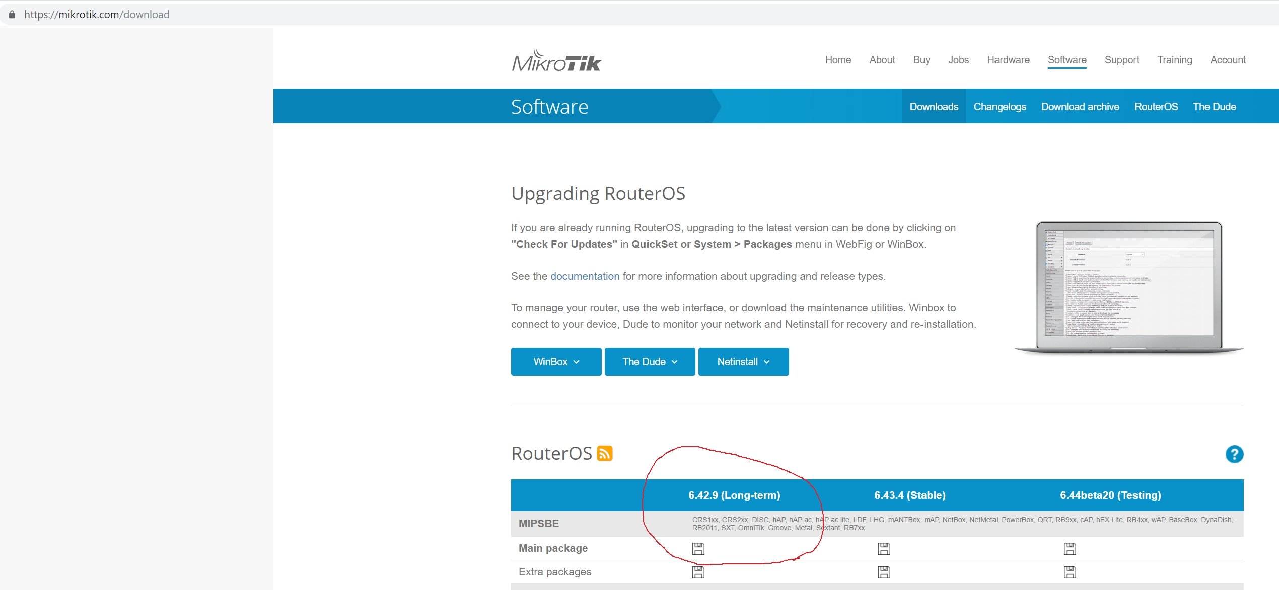
Step 2A - Download the Latest Mikrotik RouterOS for the RB493G
We will begin by downloading the latest version of RouterOS into the Downloads folder of our PC, so we can later upload RouterOS onto the RB493G. Go to Mikrotik.com in your browser, then click on 'Software'. This will bring you to a list of RouterOS versions available to download. Select the latest long term version for a MIPSBE architecture device (RB4xx) and download that to your PC's Downloads folder:
Step 2B - Download the openwrt Images for the RB493G
The current releases (as of November 2018) of the openwrt images for the RB493G are located at:
http://downloads.openwrt.org/releases/18.06.1/targets/ar71xx/mikrotik/
You will need just two files from that archive:
- openwrt-18.06.1-ar71xx-mikrotik-vmlinux-initramfs-lzma.elf
- openwrt-18.06.1-ar71xx-mikrotik-nand-large-squashfs-sysupgrade.bin
If you are working on an RB450G, it uses the exact same two files.
The initramfs file is used temporarily to initially boot the RB493G into openwrt during installation. The sysupgrade.bin file contains the full image that will be permanently stored in the NAND flash of the RB493G.
If you are working on a RouterBoard other than the RB493G or RB450G, the above filenames may be different. See the
Mikrotik Table of Hardware - Firmware Downloads
for the specific file names to be used for any of the openwrt supported Mikrotik RouterBoards.
Step 2C - Download a Copy of Tiny PXE
Tiny PXE is a very small DHCP/BOOTP/TFTP Server that we will run on our Windows 10 PC to install openwrt on the RB493G. It is freeware that can be freely downloaded. It does not need to be installed into Windows since it is a 'portable' application that can simply be run from the folder where it was downloaded. Download it from:
http://reboot.pro/files/file/303-tiny-pxe-server/
After downloading the pxesrv.zip file, unzip it into a known location (such as your Downloads folder). This will create a folder named 'pxesrv' in your Downloads folder.
Step 2D - Download and Install a Copy of PuTTY
This software is optional: it can be skipped, but will leave you blind to the netboot process on the RB493G. PuTTY is a freeware Windows terminal program we will use to login to the debug RS232 serial terminal of the RB493G. Download and install the appropriate (32 bit or 64 bit, depending on your Windows OS) .msi file from:
https://www.chiark.greenend.org.uk/~sgtatham/putty/latest.html
We now have a total of 3 files and one folder that we have stored in our PC's Downloads folder that will we use to perform the upgrade:
- routeros-mipsbe-6.42.9.npk - the latest Mikrotik RouterOS (includes WinBox)
- sysupgrade.bin - the permanent version of openwrt for the RB493G
- initramfs-lzma.elf - the temporary version of openwrt used to install openwrt
- The pxesrv folder that contains the pxesrv.exe file (Tiny PXE).
Step 3 - Reset the RB493G to Its Default Settings
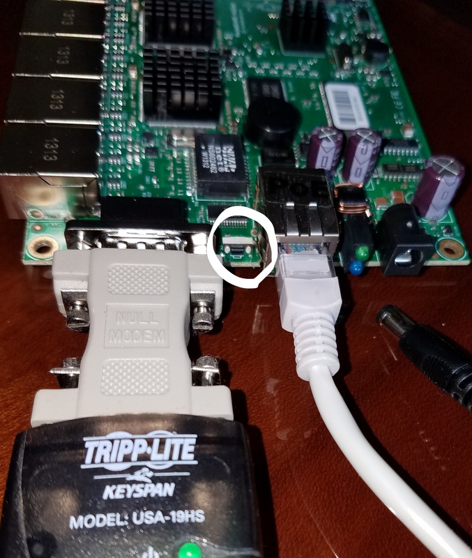
Connect an Ethernet cable from your existing switch/router to the ether1 port of the RB493G (ether1 is the single Ethernet port between the power conenctor and the serial connector), find the reset button on the RB493G (between the serial connector and the ether1 connector), depress the reset button (use a pencil), and apply (connect) power to the RB493G. Continue to hold the reset button depressed for at least 10 seconds immediately after connecting power, until the green light extinguishes: this will erase all prior setup in the RB493G and configure it to the default RB493G settings.
Be patient: this takes quite awhile to complete once the green light extinguishes. You will eventually see all the lights flash on the ethernet ports, then settle out. The two ethernet lights on the ether1 port connector will finally start flashing from activity on your network.
Step 4 - Configure Your Laptop/PC Ethernet to Talk to the RB493G
These instructions presume you have already connected an Ethernet cable from your existing ethernet network into the ether1 port of the RB493G and the RB493G is powered on. Please note the default setting of the RB493G does NOT enable a DHCP server or client on any of the Ethernet ports: only the ether1 port can be accessed (without DHCP), and only at the default Mikrotik IP address of 192.168.88.1. With the default RB493G settings, no other Ethernet ports are active on the RB493G.
These instructions presume your existing router is set up to provide DHCP to any PC connected to your network. However, these instructions presume your existing router uses some IP address range other than 192.168.88.X (the default IP address range used by Mikrotik) or 192.168.1.X (the default IP address range used by openwrt).
Since neither DHCP client or server is enabled on the RB493G, your PC will NOT be able to talk to the RB493G until your PC is setup to access the 192.168.88.X network. You therefore need to reconfigure your Windows 10 PC Ethernet settings so your PC's Ethernet is talking to BOTH your local network and the RB493G.
In addition, we want to prepare for the default IP address range of openwrt so we can easily plug into the ether2-ether9 ports during the openwrt installation. Openwrt will initially install the RB493G at IP address 192.168.1.1 so we will also set up the PC's Ethernet card to access the 192.168.1.X address range.
To review, we will now set up our PC/laptop Ethernet 'card' to have 3 simultaneous IP addresses at once:
- The same address our PC/laptop had originally on our existing Ethernet network.
- An address compatible with the default Mikrotik RouterOS 192.168.88.1 address on ether1.
- An address compatible with the default openwrt 192.168.1.1 address on ether2 - ether9.
Windows 10 will allow a network card to be at multiple IP addresses at the same time. However, in order to use this feature, only hardwired IP addresses can be used on that network card: DHCP cannot be used with multiple IP addresses.
Open a command prompt window in Windows: go to Windows Start->Windows System->Command Prompt.
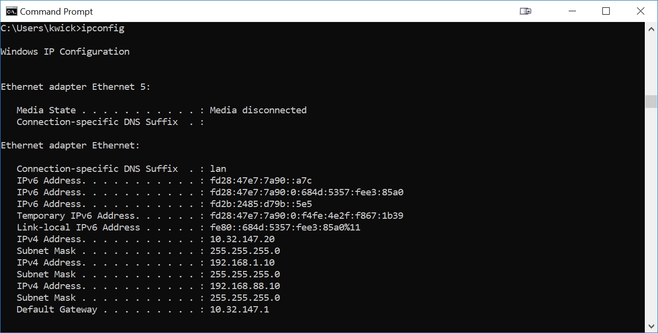
Type in the command 'ipconfig'. You will see results similar to:
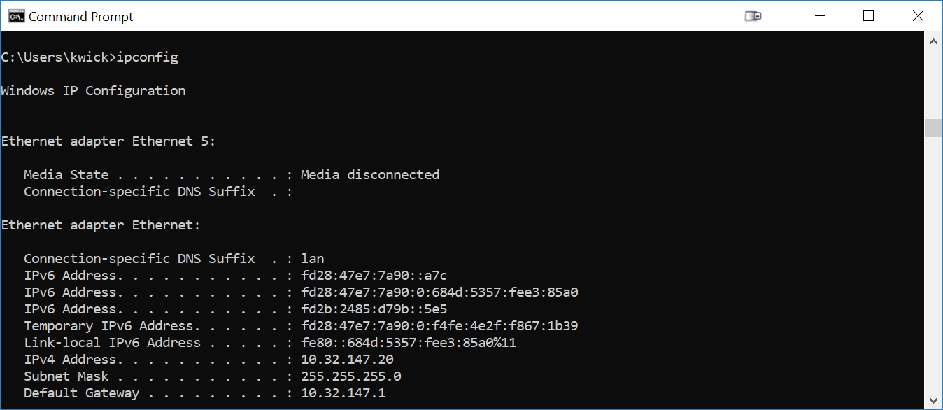
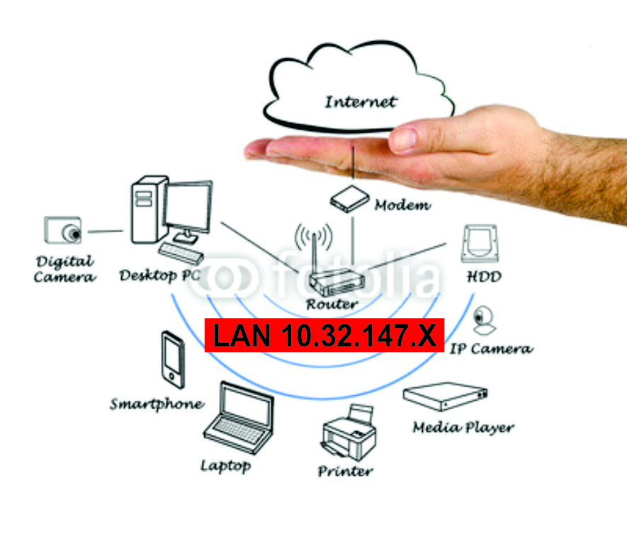
Note the 'IPV4 Address' in the above output from ipconfig: my Ethernet port is set (by DHCP) to an address of 10.32.147.20. Your PC's Ethernet will assuredly be at a different address than this. We will now change the Ethernet port settings to force the Ethernet port of my PC to 10.32.147.20 (instead of getting it from DHCP). We will also give it an IPV4 address of of 192.168.1.10 (for openwrt) and 192.168.88.10 (for RouterOS).
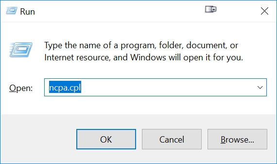
Open Windows 10 Network Connections: press the Windows Button on your keyboard, plus the 'R' key. This will open the Windows Run popup. Type ncpa.cpl, then press OK:
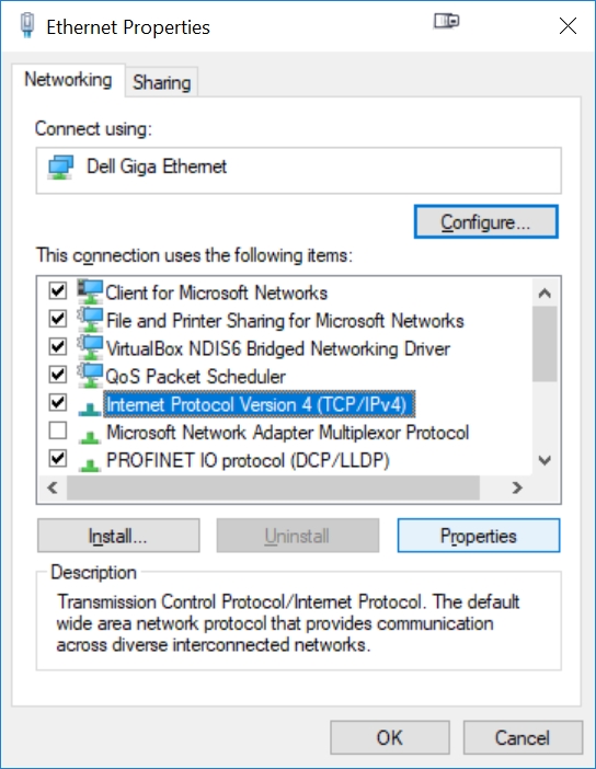
Right click your Ethernet connection, press Properties. This will bring up Ethernet Properties, then click on 'Internet Protocol Version 4 (TCP/IPv4), then the Properties button:
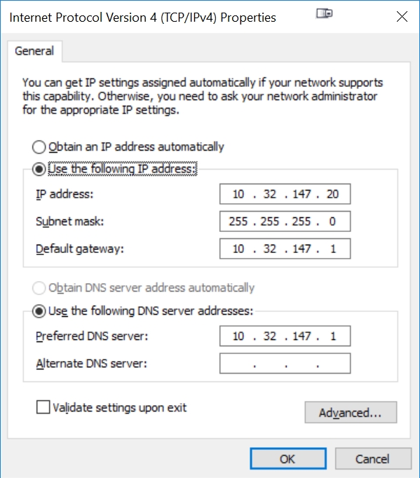
Click on the 'Use Following IP Address' and 'Use Following DNS Server Address' radio buttons to hardwire the primary IP address of your PC's Internet. Use the same IP addresses that you saw from the earlier 'ipconfig' command (see above, but use YOUR IP addresses, not those shown here)
Now click on the 'Advanced' button, then the 'Add' button of 'IP Addresses'. Enter the same IP address 192.168.1.10 shown here:
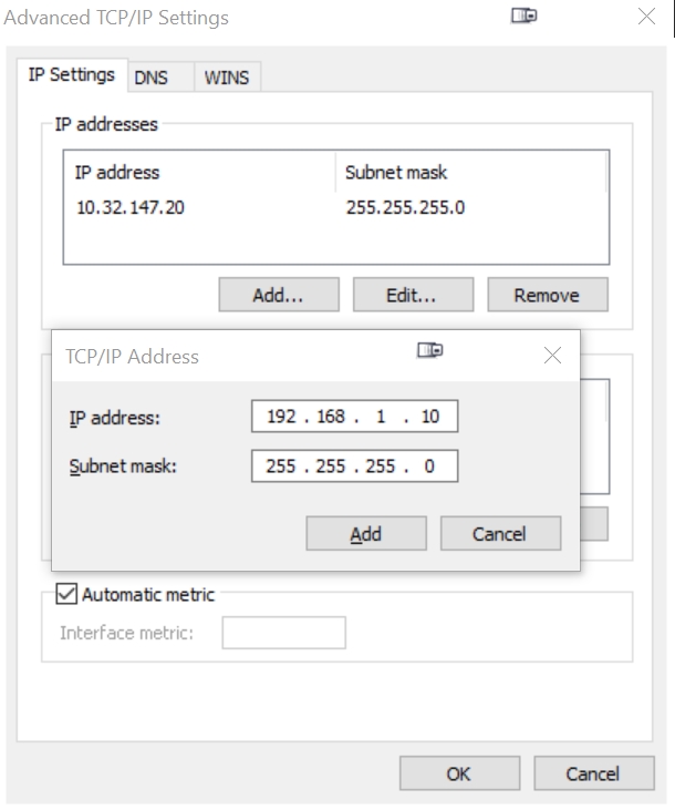
Press Add, the press Add again so we can add the next IP address 192.168.88.10 shown here:
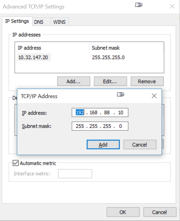
Press Add. You will now have 3 IP addresses listed in the 'IP addresses' box above: your original IP address, 192.168.1.10, and 192.168.88.10.
Press OK, then OK, then Close to get out of the IP address settings of Windows 10.
If you run ipconfig again in your command window, you will now see that your Ethernet has three simultaneous IPV4 addresses assigned:
Step 5 - Backup the RB493G License Before You Overwrite Anything
Before you remove the existing RouterOS from the RB493G (by replacing with openwrt), you should consider saving the RouterOS license file in case you'd like to re-install RouterOS at a later date.
We'll use the Mikrotik winbox app to save the exisiting RouterOS license. Note you cannot use the Mikrotik 'webfig' web interface to save the license: only the stand-alone Windows application 'winbox' contains the feature to export your Mikrotik license file.
It is best to download a copy of winbox onto your PC by using the web interface of webfig to get a copy of winbox. Do not load a copy of winbox off the Internet since that may not be compatible with the RouterOS version running on the RB493G.
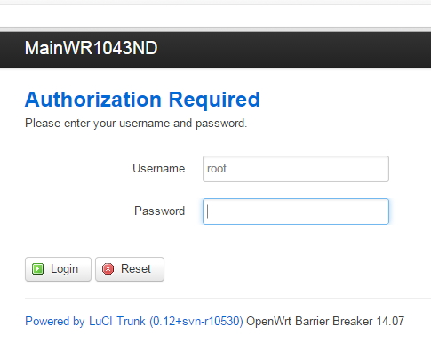
Now that our PC is capable of talking to the 192.168.88.X network, we will use a web browser, such as Chrome, to access the built-in 'webfig' web pages of the RB493G router. Enter the URL '192.168.88.1' into your web browser:
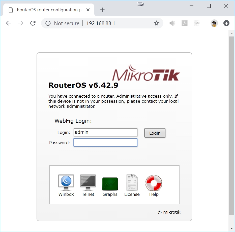
The default login is 'admin' and the password is empty. Press the Login button to enter the WebFig pages.
Step 5A - Load the Latest RouterOS Into the RB493G
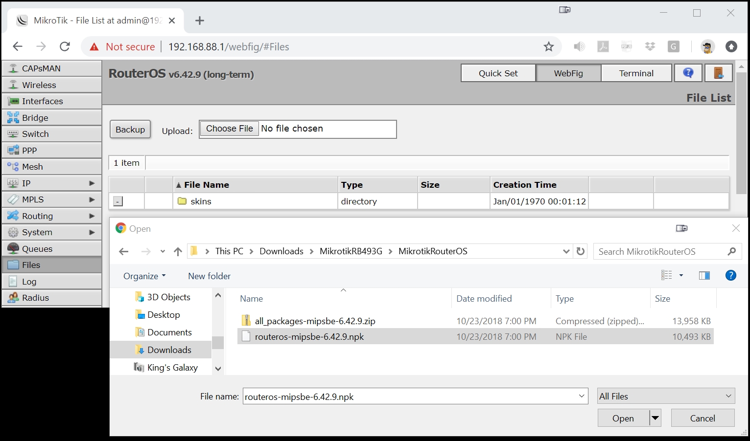
Now that you are in Mikrotik 'webfig', click on Files, then Choose File, then navigate to the Downloads folder on your PC where you stored the latest version of RouterOS that you previously downloaded from the Mikrotik website (see Step 2A above), then Open the routeros file.
Once the upload completes, click on 'System' then 'Reboot' in WebFig. This will reboot the router and install the newest version of RouterOS.
The RB493G will reboot and take quite a few minutes to write the new RouterOS image into the NAND of the RB493G. Be patient and wait until the RB493G has rebooted a couple times and you can once again log into 192.168.88.1. Do NOT power off the RB493G.
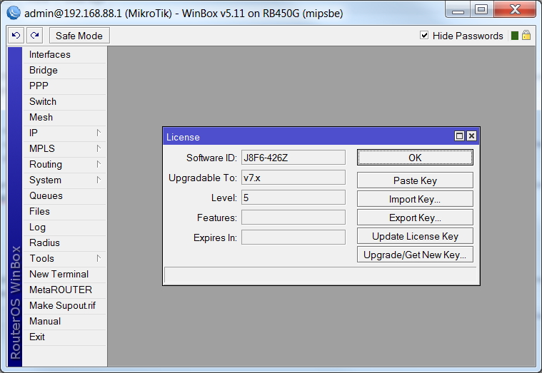
Step 5B - Use WinBox to Export the License Key
Once the RB493G has fully updated and rebooted, do NOT login. Instead, click on 'Winbox' in the WebFig login . This will save a copy of WinBox to your Downloads folder on your PC.
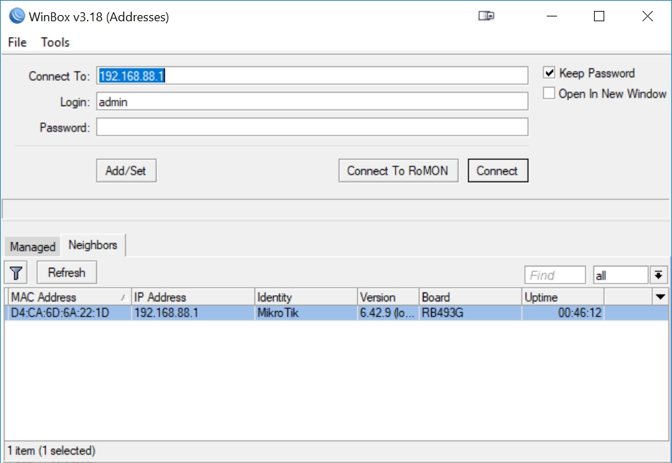
Use Microsoft File Explorer to go to your Downloads folder and click on Winbox.exe. This will open the Winbox Windows application to its login page. Enter 'admin' as the Login, with no password, then press Connect:
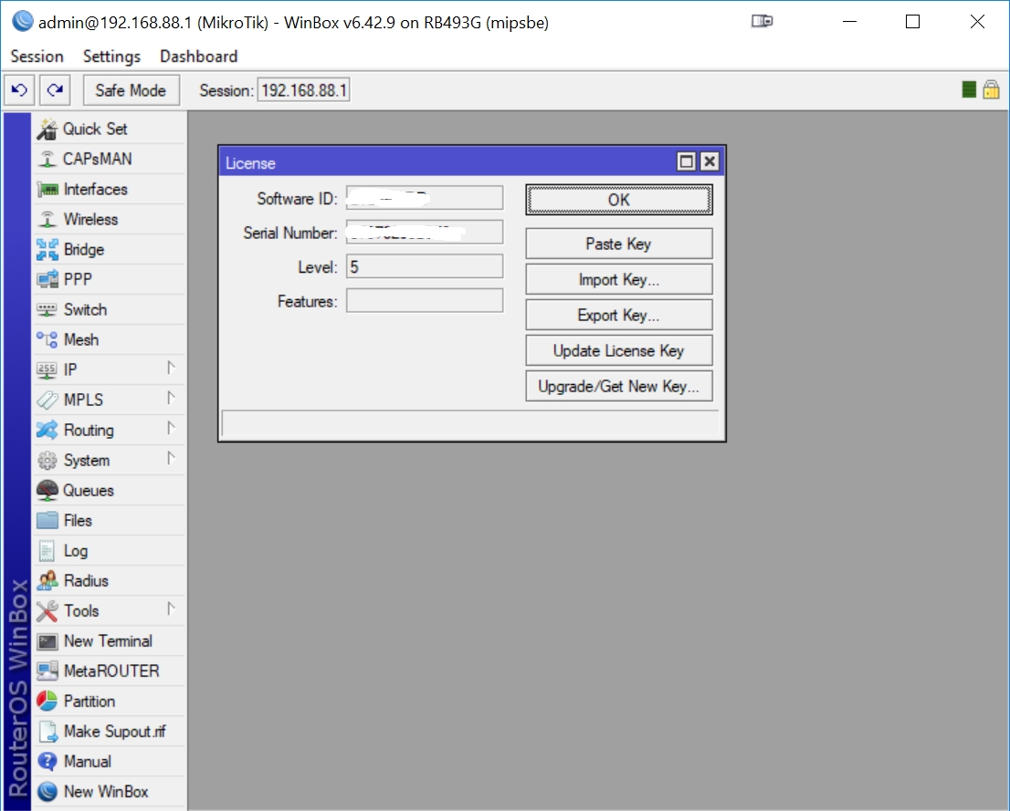
Once you are in WinBox, press 'System', then 'License', then 'Export Key' to save your license to a file in the Downloads folder of your PC:
If you do need to re-install RouterOS again, it is a fairly easy process to use Mikrotik's netinstall utility. Please refer to our post: Using Mikrotik netinstall to install RouterOS.
Step 6 - Configure and Connect to the RB493G Serial Port
This step is optional, but highly recommended so you can view what is happening on the RB493G serial port console terminal.
Attach the Tripp Lite Keyspan USA-19HS RS232 Adapter to your laptop's USB port and the serial port of the RB493G. You will need to use a null modem adapter to connect the USA-19HS DB-9 serial connector to the RB493G DB-9 serial connector (see the Step 3 picture above).
When the USA-19HS is first attached to the USB port of your PC, Windows 10 will automatically download and install a driver for the device - so it's important to perform this initial installation while your laptop is still connected to the Internet. If you are running Windows 7 or earlier, you may need to manually download and install the USA-19HS driver from the Internet.
The USA-19HS adapter will be installed to one COM port of your PC: pay attention during installation since you will need to use that precise COM port to set up putty.
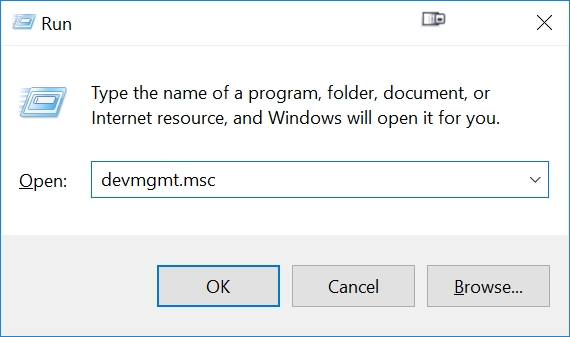
If you did not notice the COM port that the serial adapter is associated to, you can use the Windows Device Manager to verify exactly which COM port is associated with the USA-19HS. Press the Windows Key, then the 'R' key, then type 'devmgmt.msc':
Scroll down to Ports in the Device manager to determine which COM port is associated with the USA-19HS:
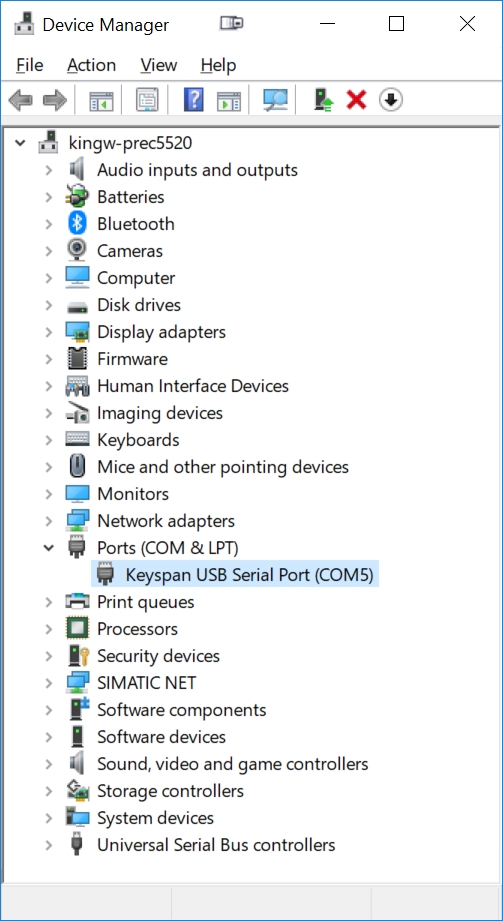
In this case, we can see above that Windows installed the USA-19HS at COM port 5. This is the COM port we will use to set up PuTTY.
Now go to Windows Start->Putty and open the Putty application. Click on the 'Serial' radio button in the PuTTY Configuration popup:
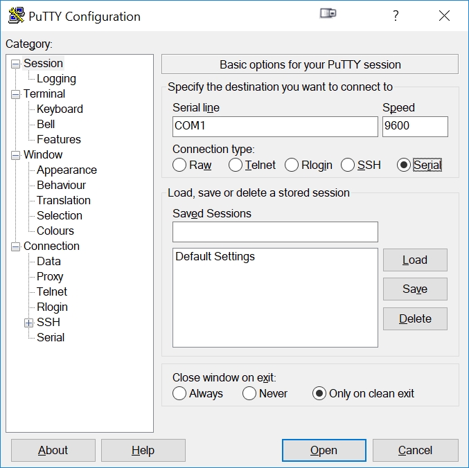
Note we have not yet configured the correct serial settings in the above screen shot: the COM1 'Serial line' is the wrong COM port, and the 'Speed' should be 115200. So under the left-hand 'Category' list, click on 'Serial'. This will bring you to the screen to configure the serial settings:
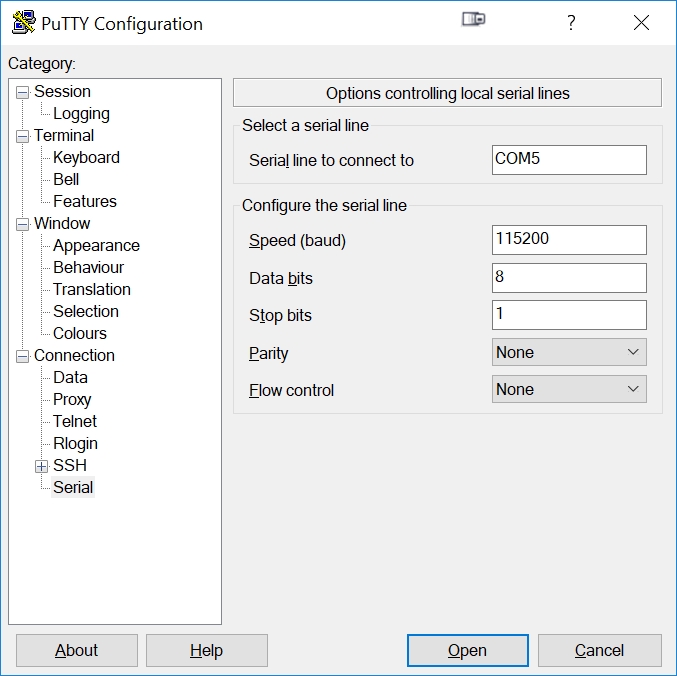
Set the serial line to the COM port you noted above from the Windows Device Manager (COM5 in our example above). Baud is 115200, no parity, 1 stop bit, 8 bits and no flow control.
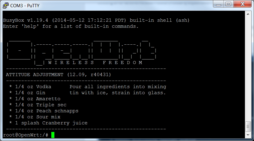
Press the Open button to open a PuTTY terminal window in Windows. You will see a (blank) window like:
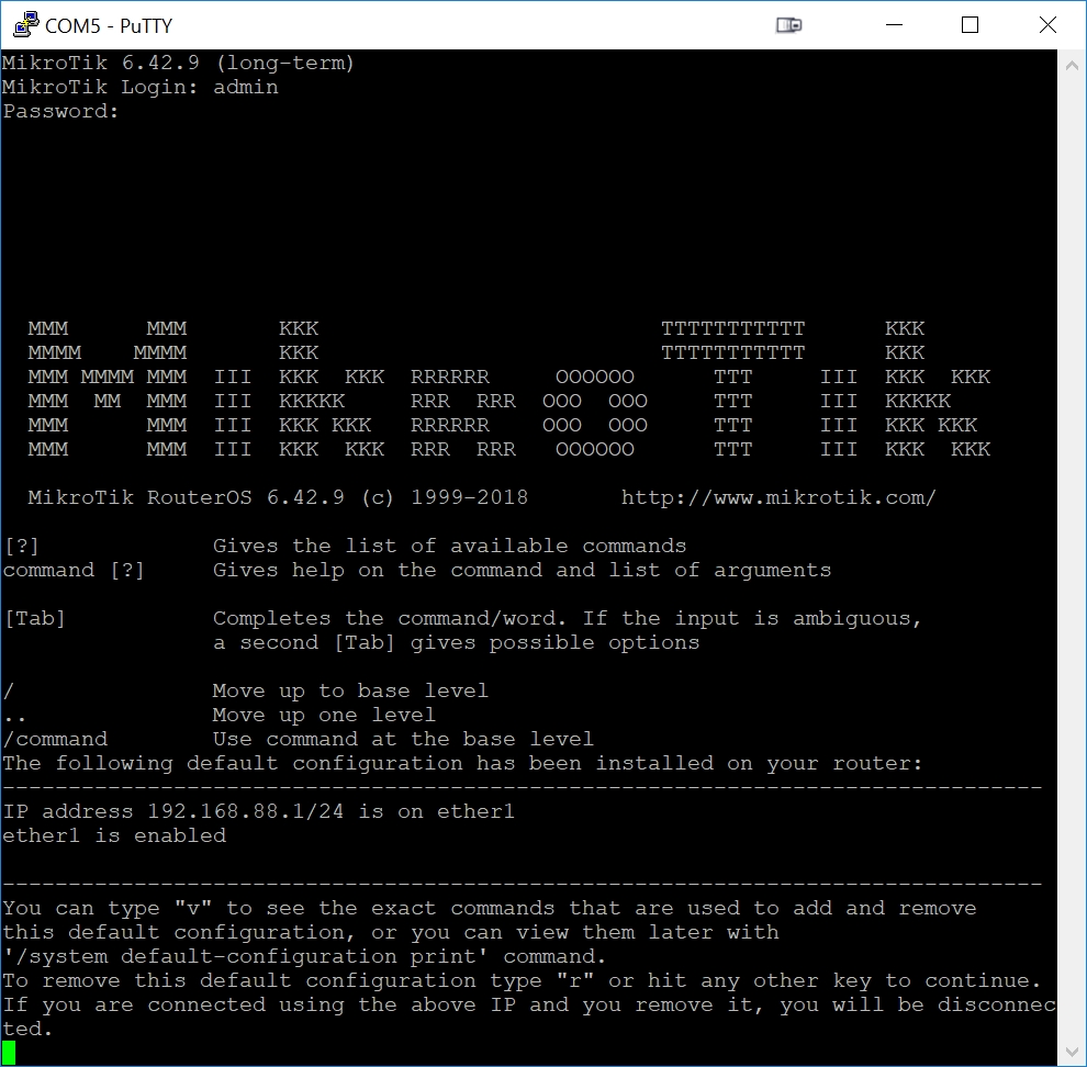
Move your cursor to the PuTTY terminal window and press the Enter key on your keyboard. You will get a prompt for the MikroTik login, such as:
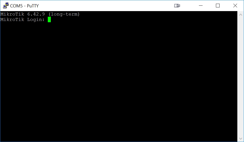
To prove that PuTTY is accepting keyboard input successfully, type in 'admin' as the Login and press Enter for the Password (no password). You will get the MikroTik serial port login page:
Step 7 - Run TinyPXE
The RB493G will optionally use the Preboot Execution Environment (PXE) to boot an image from the network. This ability to boot an image from the network (PXE) is the method used to install openwrt.
PXE consists of three distinct software packages that are individually served up by an existing device (such as a router) on a network:
- A DHCP (Dynamic Host Control Protocol) server that provides a booting PC (the RB493G) with an IP address to use on the local network. DHCP is likely used by every device connected to your network: most devices get their IP address from the DHCP server on the local network (your router).
- A BOOTP (Boot Protocol) server that provides a booting PC (the RB493G) with the name and location of the network image file to get over the network. BOOTP is only used by PXE devices connected to your network (likely ONLY the RB493G), and only used for the short period of time that those devices are booting.
- A TFTP (Trivial File Transfer Protocol) server that sends the network image file to the booting PC. TFTP can be used to transfer files between devices in other situations, however your Windows PCs are using their own built-in protocols (other than TFTP) to perform all file transfers on your network. So for all practical purposes, TFTP is only used by PXE devices connected to your network (likely ONLY the RB493G), and only used for the short period of time that those devices are booting.
Virtually all routers offer the ability to serve DHCP, however many (home) routers do not have BOOTP or TFTP capabilities.
In order to download the new openwrt image to the RB493G, we will need an existing device on the network that serves up all three protocols above.
Since there are an endless number of routers that may already exist on a network, and the instructions to set up DHCP, BOOTP, and TFTP all vary from one router to another, we will instead temporarily disconnect our laptop from our local network, connect an Ethernet cable between our laptop and the RB493G, and run a small piece of software that will provide DHCP, BOOTP, and TFTP while we download the image to the RB493G.
There are multiple choices of PXE environments that will run on a Windows 10 PC, such as tftpd32, serva and tinyPXE. TinyPXE is free, has full support for the BOOTP style netboot (unlike the other options listed above) and is very simple to use: perfect for this application.
Step 7A - Download and Unzip TinyPXE
See Step 2C above for details on installing Tiny PXE (pxesrv.exe).
Step 7B - Modify the TinyPXE Config File to Enable RFC951 (BOOTP)
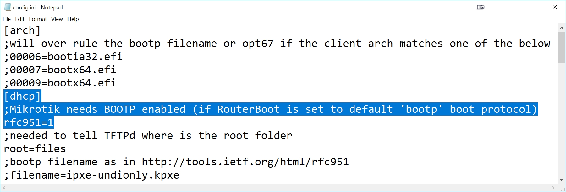
Use an editor such as notepad to edit the TinyPXE config.ini file. The config.ini file is located in the same folder as the TinyPXE executable (pxesrv.exe). Scroll down below the [dhcp] section of the confiig.ini file and add the following line anywhere in the [dhcp] section:
rfc951=1Following is an example of the top section of a modified TinyPXE config.ini file. The [dhcp] section identifier and two added lines for the Mikrotik are highlighted below. Note the first line added is a comment (starts with ';'):
Step 7C - Disconnect Ethernet Cables from Your Existing Router/Switch
Before we run Tiny PXE, it is VERY important to isolate your PC/laptop from your existing network and ensure your laptop is ONLY connected to the ether1 port of the RB493G. Since your existing network already has a DHCP server running, you cannot run a second DHCP server on the same network: the two DHCP servers will compete with each other and result in an unstable network setup. Do NOT start Tiny PXE until you have rewired your Ethernet cables to isolate the laptop from your existing network.
So we will now isolate the laptop and RB493G from the rest of the network by disconnecting the laptop and RB493G from your existing network. After removing the Ethernet cables from the RB493G and your laptop/PC, connect an Ethernet cable from your laptop/PC directly to the RB493G ether1 port. Make sure the WiFi is off on your laptop too.
Step 7D - Start pxesrv.exe
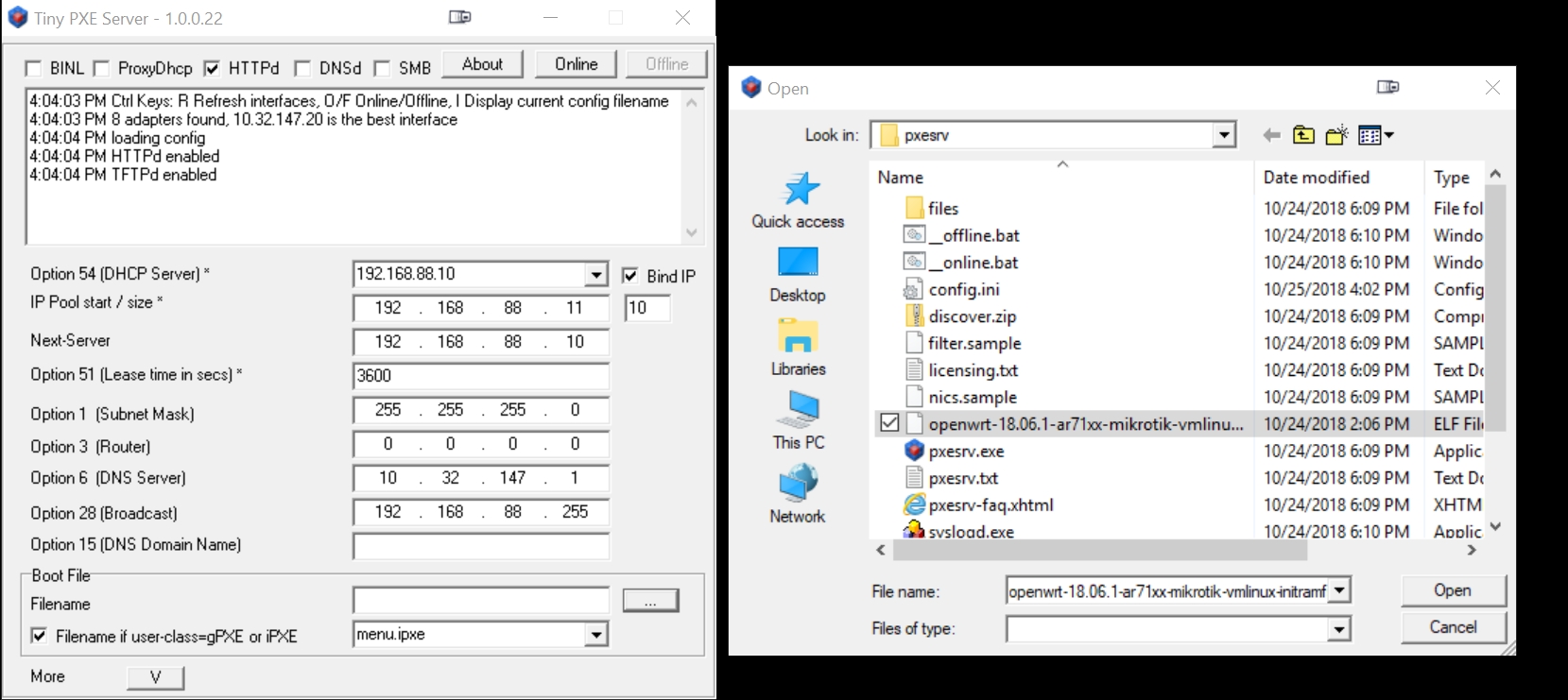
Use Windows Explorer (press the Windows button on your keyboard plus the 'E' key) to go to the pxesrv folder in your Downloads folder. Click on the pxesrv.exe file to start up Tiny PXE. Windows and/or your antivirus may ask about running the application and modifying the firewall: be sure to respond yes to any requested changes.
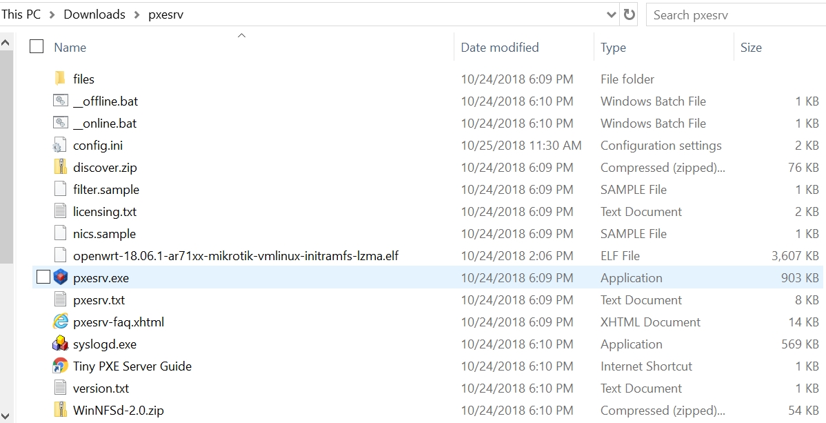
Note the openwrt initramfs-lzma.elf file previously copied into this same folder.
The Tiny PXE Startup window will automatically select any one of your connected Ethernet interfaces. Note below that I have selected the 192.168.88.10 interface (the Mikrotik interface) as the interface to run the DHCP server (not absolutely necessary, but makes the most sense):
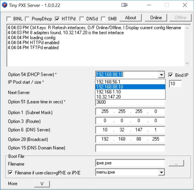
Select the previously downloaded (in Step 2B) openwrt vmlinux-initramfs-lzma.elf file that we will netboot into the RB493G:
Disable (uncheck) the 'Filename if user-class=gPXE or iPXE'.
And finally, start TinyPXE by pressing the 'Online' button:
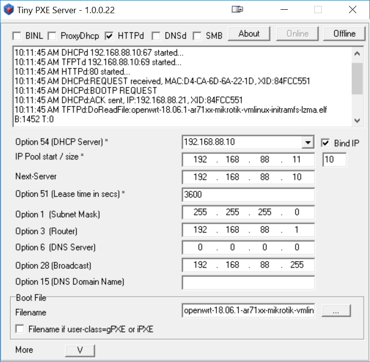
Note that after Tiny PXE was put online in the above example, a successful DHCPd:ACK and TFTPd DoReadFile occurred: the RB493G booted from the initramfs-lzma.elf file. This will occur as soon as we enable the RB493G for a network boot from DHCP (the next step).
If you cannot get TinyPXE to work (if you can't get TinyPXE to recognize the booting RB493G in the next step), the first thing to check is your firewall settings. It is highly advisable to try temporarily turning off your firewall if you have any problems here.
Step 8, Option 1 - Boot the RB493G from the Network Using Reset Button
The simplest method to boot the RB493G from the network is to hold the RB493G reset button immediately after powering up the RB493G. When the reset button is pressed at powerup, the default settings of the RB493G RouterBoot will first attempt to run BOOTP, then boot from NAND flash if the BOOTP netboot fails.
Therefore, since we have enabled rfc951 BOOTP netboot in TinyPXE above, all we need to do is to power off (unplug) the RB493G, hold the reset button, then power on (plug in) the RB493G. After a few seconds (continue to hold the reset button after plugging power in), the RB493G will begin checking for a BOOTP/TFTP server.
Step 8, Option 2 - Configure the RB493G to Boot from the Network using DHCP
This method of booting from the network is required if NOT using rfc951 BOOTP netboot (a TinyPXE config.ini option), but instead using DHCP/BOOTP netboot. If using DHCP/BOOTP instead of rfc951 BOOTP, we need to use the serial console to modify the Mikrotik RouterBoot settings to boot exclusively from the network, and to use DHCP boot protocol instead of the BOOTP boot protocol.
Unplug the power to the RB493G, wait a couple seconds, then plug the power in. This will reboot the RB493G.
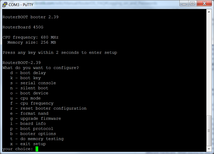
You'll have a couple seconds to press any key after the reboot. This is not much time, so I recommend moving your cursor to the PuTTY window in advance so the PuTTY terminal window has focus and your keyboard input will then go to PuTTY (the RB493G).
Here we are in Putty after we pressed a key within a couple seconds of the RB493G bootup:
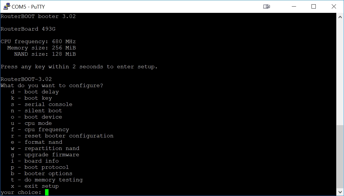
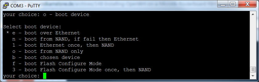
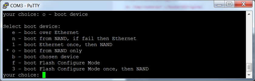
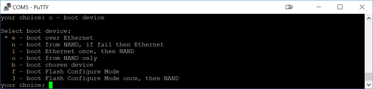
Now we want to convince the RB493G to quit booting from its flash (called NAND) and instead boot from the Network. Press 'o', then 'e'. Press 'o' again to see if you were successful at getting the Ethernet selected as our boot source: we should see the 'e' as the highlighted selection. The Enter key will exit this submenu.
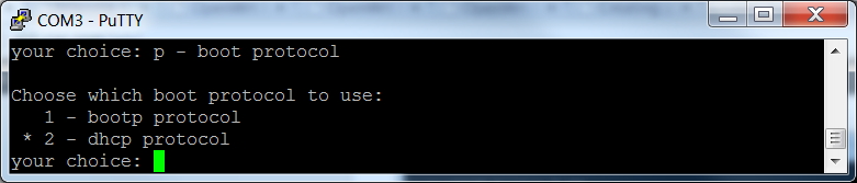
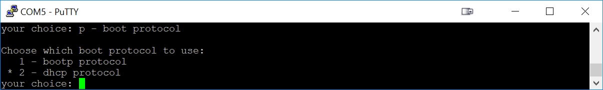
And we also want the RB493G to use DHCP (PXE boot) instead of BOOTP when it is booting from the network. Press 'p', then '2'. Press 'p' again to verify your success. The Enter key will exit this submenu.
Press 'x' (exit setup) to save your settings and reboot the RB450G.
Now the RB493G is patiently waiting to boot from the network.
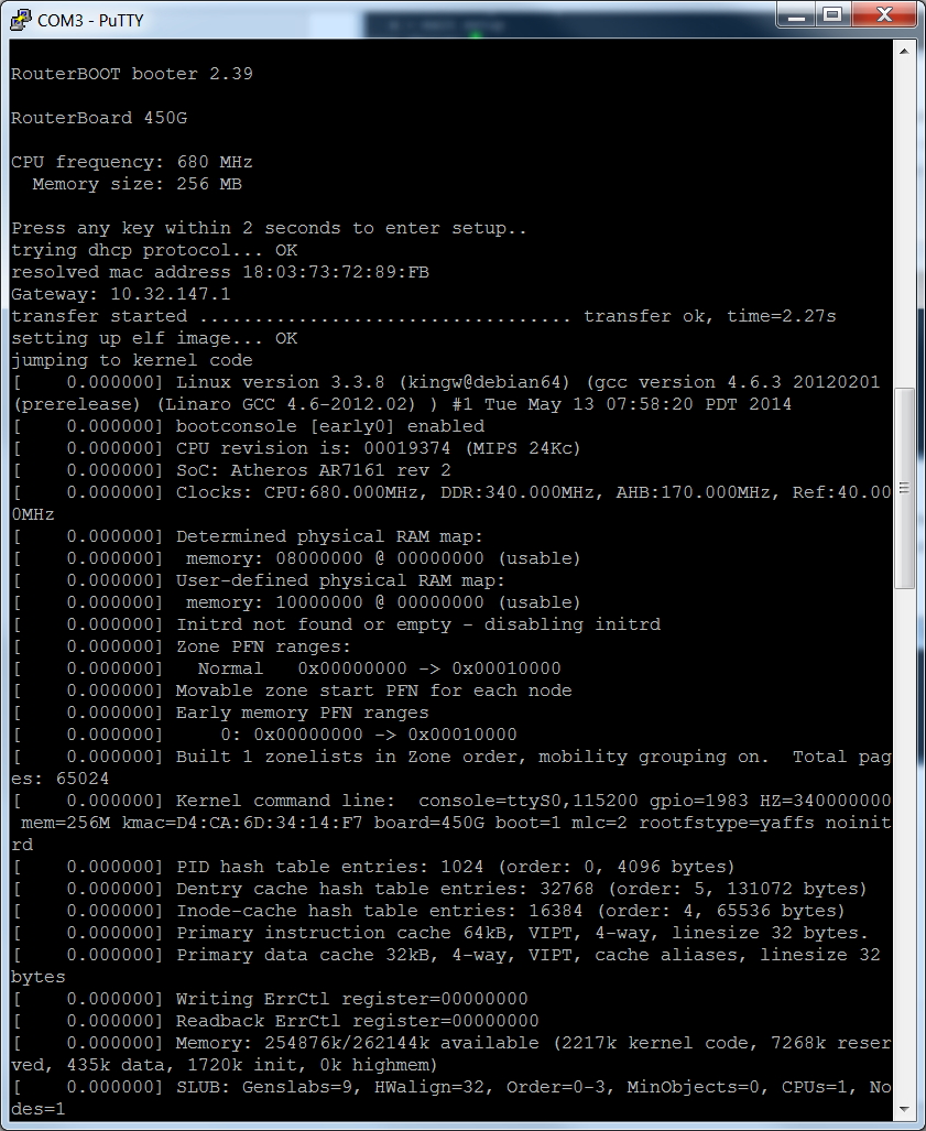
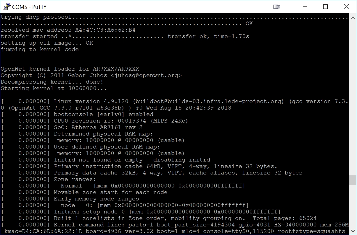
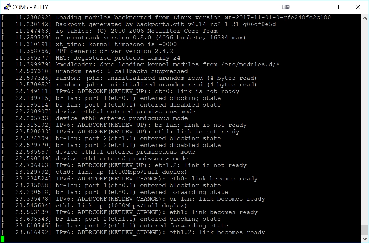
Step 9 - The Download of the openwrt initramfs File Starts and Completes
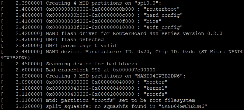
Once the DHCP/BOOTP/TFTP TinyPXE server is running and the RB493G has been enabled for network boot, the netboot of the initramfs file will begin immediately. This is the serial console output during the netboot of openwrt (assuming you have a serial adapter connected to the serial console):
Step 10 - Perform openwrt SysUpgrade to Permanently Write to NAND
At this point, the RB493G is now running a temporary copy of openwrt: it is only in the RB493G RAM and has not yet been permanently written to the RB493G NAND flash. If we power down the RB493G, the openwrt currently in RAM will be lost and we will once again need to load the initramfs file into the RB493G using TinyPXE.
We will use this temporary version of openwrt to perform a 'SysUpgrade' that permanently writes the sysupgrade.bin file into the RB493G NAND flash. This step is irreversible: the Mikrotik RouterOS will be permanently erased from the NAND flash.
In order to login to openwrt, our laptop now needs to be plugged into any of the ether2 through ether9 ports.
Disconnect the Ethernet cable from the ether1 port and reconnect to any of the ether2 - ether9 ports.
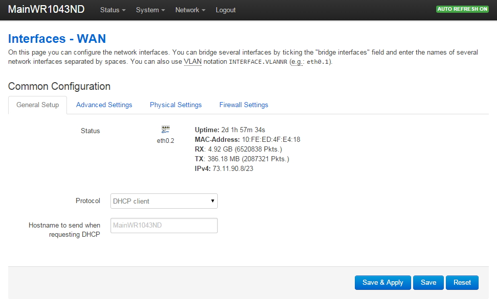
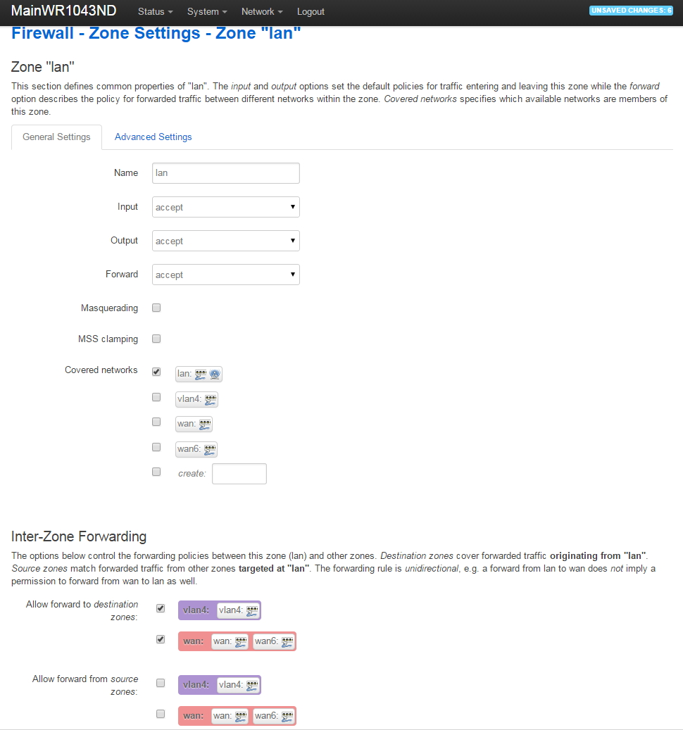
Enter the IP address 192.168.1.1 into your web browser URL to login to openwrt:
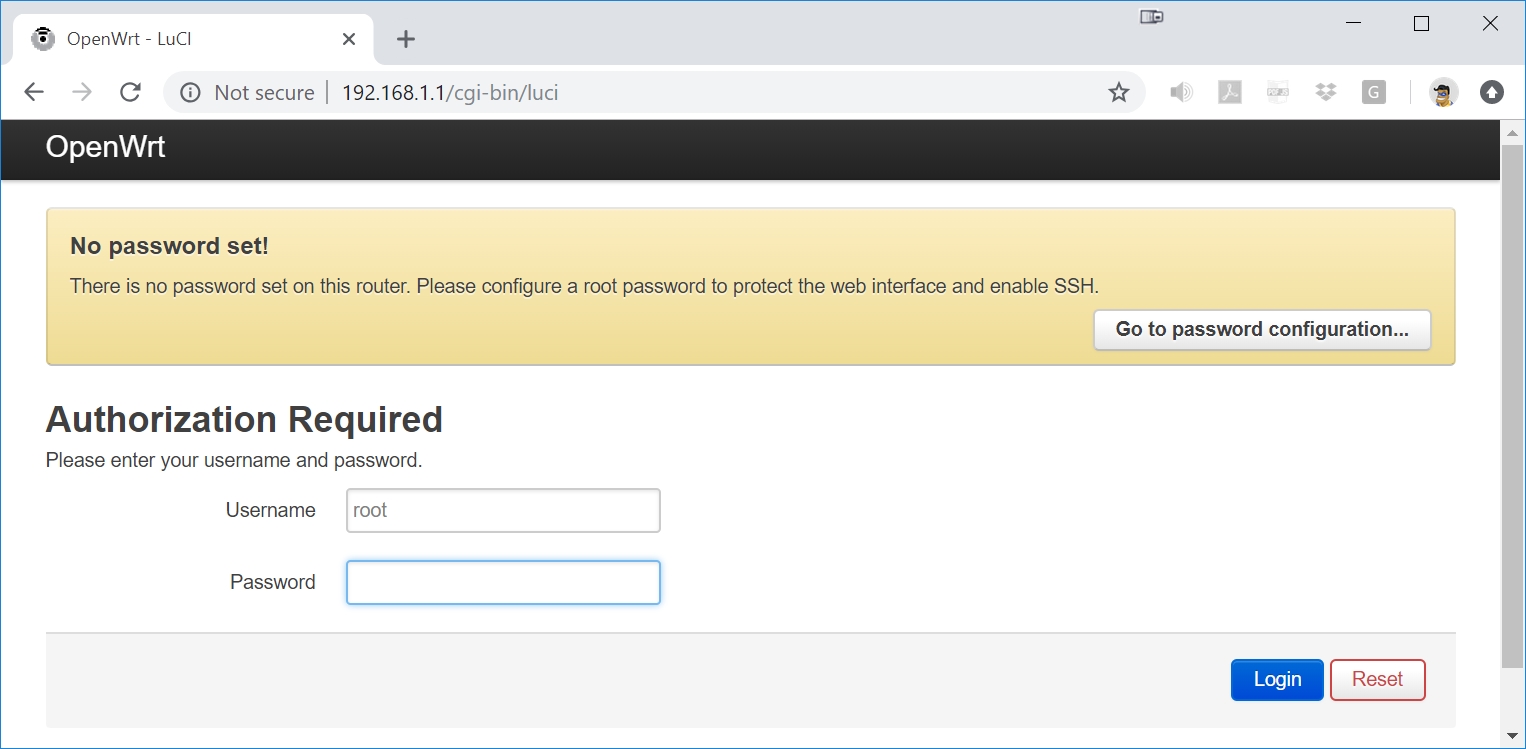
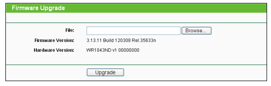
Press the Login button and go to System->Backup/Flash Firmware:
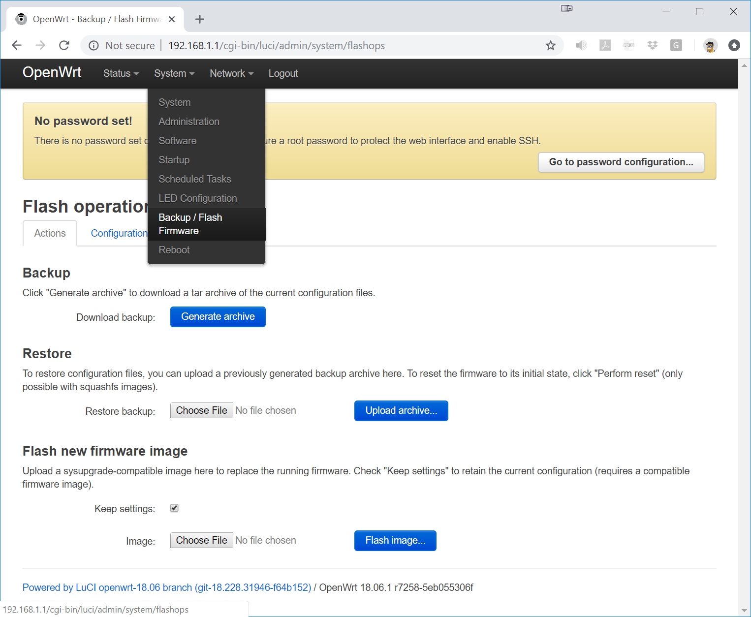
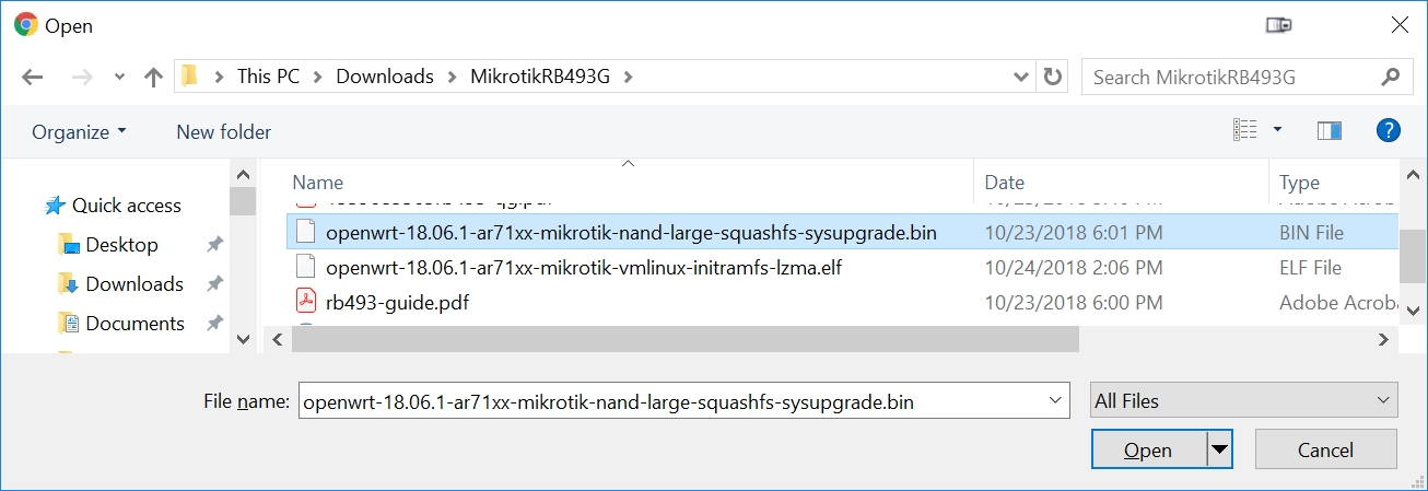
Press the Choose File button and select the sysupgrade.bin file that you saved to the Downloads folder in Step 2B:
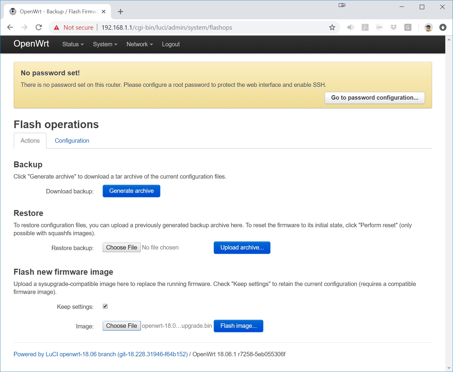
Press the Flash Image button:
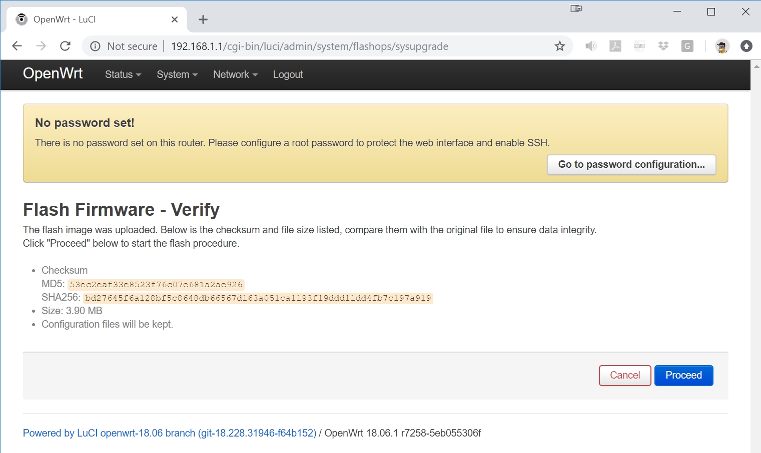
Press the Proceed button after verifying the .bin file details:
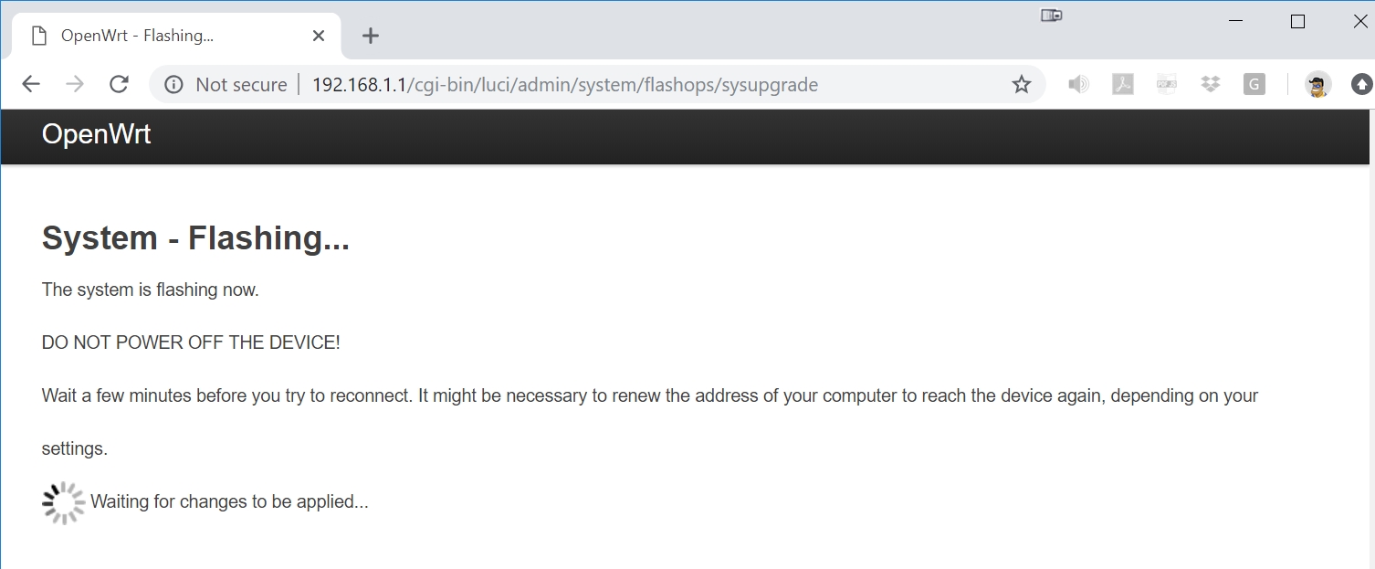
While flashing, you will see the following screen, and then the RB493G will automatically reboot. Watch the PuTTY serial port to know when the flashing has completed since the following screen will not change:
Step 11 - Reconfigure the RB493G to Boot from NAND
If you used Step 8, Option 2 where you reconfigured the MikroTik RouterBoot to always boot from the network, you now need to revert that setting back to its default value to boot from NAND. If you instead used Step 8, Option 1 and simply held the reset button to force a BOOTP netboot, you will not need to perform this final configuration change step here.
After you have seen the RB493G automatically reboot on the PuTTY screen after the preceding firmware flash, the RB493G will once again try to boot from the Network (assuming you used Step 8, Option 2).
We now need to tell the MikroTik RouterBoot to start booting from NAND again: there is no longer any need to boot from the network.
Unplug the RB493G power, wait a couple seconds, then plug the power in. This will reboot the RB493G.
You'll have a couple seconds to press any key after the reboot. This is not much time, so I recommend moving your cursor to the PuTTY window in advance so the PuTTY terminal window has focus and your keyboard input will then go to PuTTY (the RB493G).
Now we want to reset the RB493G to boot from NAND flash. Press 'o', then 'n'. Press 'o' again to see if you were successful at getting the NAND selected as our boot source: we should see the 'n' as the highlighted selection. The Enter key will exit this submenu.

Press 'x' to exit setup. You are done. Congratulations!